DMA demo for ADC with NXP FRDM MCX A346
Introduction
This article shows how to modify an NXP's lpadc_dma SDK example to create a breadboard application. It is a follow up to my previous articles on lpadc_polling and lpadc_interrupt. For this tutorial I'll be using an light dependent resistor (LDR) again in an analog-to-digital converter (ADC) setup.
In the article about lpadc_polling I explained why I made some deliberate adjustments to the SDK example and I gave a step-by-step instruction on how to use the IDE. In the article about lpadc_interrupt I explained how the LPADC temporarily stores measurement results in the FIFO buffer.
In this article, we'll take the next step to improve the real-time determinism of our projects by using Direct Memory Access (DMA). DMA is intended to reduce the amount of time the CPU has switch between tasks. Instead of the CPU, it is the DMA which retrieves the results from the FIFO and temporarily stores them in RAM until a certain number of conversions has been stored. This number is set in advance by the developer. Because DMA reduces task switching by the CPU it is important for dealing with real world applications where large amounts of data need to be processed in a short amount of time, without the overburdening the CPU. This project is still a simple example, but in practice it is essential for managing large and complex data flows.
Prerequisites
- MCUXpresso IDE installed
- NXP FRDM MCX A346 board
- Breadboard, 3 male jumper wires, 1 LDR, 1 10 kΩ resistor
- Documentation, especially the MCXAP144M240F60RM Reference Manual (rev 4) (download link)
- Familiarity with the Pins Tool (see previous article)
DMA: moving data without CPU involvement
Direct Memory Access (DMA) is important for reliable real time performance in modern microcontrollers. It allows data to be moved around without consuming CPU cycles, which greatly improves real-time behavior.
Microcontrollers often need to process large amounts of data while operating under tight resource constraints. They may have a single CPU core and no hardware parallelism. Without additional hardware support, the CPU would have to handle every task one after another, including reading every ADC conversion the moment it becomes available. This limits responsiveness, increases latency, and makes timing unpredictable.
DMA solves this problem by acting as a second busmaster. It can read data from peripherals (such as ADC FIFO entries) and write it directly into RAM without the need of executing a single CPU instruction. The CPU and DMA operate in parallel on different bus paths, which means the CPU can continue running application code while the DMA moves data in the background.
Without DMA, every ADC conversion would trigger an interrupt. Each interrupt forces the CPU to stop what it is doing, save its state, run the handler, and restore the previous context. At high sample rates this overhead becomes significant and can make the system unstable or unresponsive.
With DMA, the peripheral generates DMA requests instead of CPU interrupts. The DMA engine writes each conversion result into a RAM buffer. Only when the buffer is full does the DMA trigger a single interrupt, allowing the CPU to process the data in larger, more efficient batches. The higher the sample rate and the larger the buffer, the greater the benefit: the CPU spends more time doing useful work and less time switching between tasks.
In practice, DMA allows microcontrollers to process data much more resource friendly. By collecting samples in batches, space is freed up for algorithms that require multiple data points (like it is the case with FFTs, filters, trend analysis, or detecting sudden jumps in sensor data). Many forms of signal processing only become useful when you can compare samples over time: a single reading rarely tells you whether a value is drifting, oscillating, or changing abruptly. Batch processing therefore not only reduces interrupt overhead, but also provides the time context that real time algorithms need to extract useful information from raw sensor data. DMA therefore changes not only how data is moved, but especially when the CPU needs to do work. The result is a system that is more reliable, can handle higher sample rates, and is much more scalable to more complex real-time applications.
DMA and considerations about cache memory
When browsing through the lpadc_edma SDK example, you'll notice variable names and comments related to cache handling, such as the AT_NONCACHEABLE_SECTION_ALIGN_INIT() macro and remarks in fsl_edma.c like:
"For platforms with cache, the software TCD should be placed in a non-cacheable section."
So why does the SDK put so much emphasis on avoiding cached memory for DMA?
The reason is that DMA writes data directly into RAM, without the involvement of the CPU and its cache. Cache memory is physically separate from RAM and sits closer to the CPU, making access much faster. However, because the CPU is not involved in the DMA transfer, it has no way of knowing that RAM has been updated. If the CPU previously loaded that memory region into its cache, it may continue using the old cached value instead of the new data written by the DMA engine.
This situation is known as a cache coherence problem, and it can lead to subtle and unreliable behavior: the DMA writes fresh data into RAM, but the CPU keeps reading stale data from its cache.
By placing DMA buffers and TCD structures in non-cacheable memory, both the CPU and the DMA always access the actual data stored in RAM rather than any cached copy. The TCD (Transfer Control Descriptor) is the configuration block that the DMA engine reads directly from RAM to perform a transfer. Keeping these buffers and structures non-cacheable ensures that neither the CPU nor the DMA ever works with stale data, which is essential for consistent behavior in real-time applications.
The volatile keyword
The volatile keyword is related to the previous topic, but for a completely different reason. Where cache issues arise from hardware bypassing the CPU, volatile deals with how the compiler treats variables during optimization.
A compiler tries to remove or reorder code that it believes will never be used. In embedded systems this can easily go wrong, because hardware - not the CPU - can change the value of a variable. For example, variables that are updated inside interrupt handlers may appear unused or unmodified from the compiler's point of view. The compiler only sees the main program flow. It does not automatically assume that an interrupt can modify a variable in the background.
On ARM Cortex-M microcontrollers, interrupts are triggered by the Nested Vectored Interrupt Controller (NVIC). The NVIC uses a vector table (which can be found in startup_MCXA346.c) containing function pointers to interrupt handlers. These handlers may update variables even though the compiler cannot see any direct call to those functions in the main code. Without precautions, the compiler might optimize such variables away or keep their values cached in registers, assuming they never change.
The volatile keyword tells the compiler that a variable can change at any time, outside the normal program flow. This prevents the compiler from removing the variable, caching its value in a register, or reordering accesses to it.
In the SDK example, the variable DMACounter is modified inside the DMA interrupt handler. Because the compiler cannot see that hardware will trigger this handler, DMACounter must be declared volatile to ensure the compiler always reloads its value from memory and never optimizes it away.
Code
First, configure the input pin (ADC1_A12) the same way as in the previous article, using the Pins Tool.
Below follows the code for your version of app.h (in your project folder > board). It is adapted to the situation where 16 samples are stored in RAM before an interrupt is triggered.
/*
 * Copyright 2025 NXP
 * All rights reserved.
 *
 * SPDX-License-Identifier: BSD-3-Clause
 */

#ifndef _APP_H_
#define _APP_H_

/*******************************************************************************
 * Definitions
 ******************************************************************************/
/*${macro:start}*/

/* ADC Defines */
#define DEMO_LPADC_BASE                  ADC1
#define DEMO_LPADC_IRQn                  ADC1_IRQn
#define DEMO_LPADC_IRQ_HANDLER_FUNC      ADC1_IRQHandler
#define DEMO_LPADC_USER_CHANNEL          12U
#define DEMO_LPADC_USER_CMDID            1U /* CMD1 */
#define DEMO_LPADC_VREF_SOURCE           kLPADC_ReferenceVoltageAlt3
#define DEMO_LPADC_DO_OFFSET_CALIBRATION true
#define DEMO_LPADC_USE_HIGH_RESOLUTION   false

/* EDMA Defines */
#define DEMO_DMA_BASEADDR    DMA0
#define DEMO_DMA_CHANNEL_0   0U
#define DEMO_DMA_IRQ         DMA_CH0_IRQn
#define DEMO_DMA_IRQ_HANDLER DMA_CH0_IRQHandler
#define BUFFER_LENGTH        16U
#define DEMO_DMA_REQUEST     kDma0RequestMuxAdc1FifoRequest

/* Low power timer for ADC Trigger */
#define LPTMR_TRIG_BASE         LPTMR0
#define LPTMR_TRIG_USEC_COUNT   62500U
#define LPTMR_TRIG_IRQn         LPTMR0_IRQn
#define LPTMR_TRIG_HANDLER      LPTMR0_IRQHandler
#define ADC_LPTMR_TRIG_CLOCK    kLPTMR_PrescalerClock_1
#define LPTMR_TRIG_SOURCE_CLOCK (16000U)

/*${macro:end}*/

/*******************************************************************************
 * Prototypes
 ******************************************************************************/
/*${prototype:start}*/
void BOARD_InitHardware(void);
/*${prototype:end}*/

#endif /* _APP_H_ */
Below follows the code for your version of lpadc_edma.c. It is still mainly the lpadc_edma SDK example.
/*
 * Copyright (c) 2016, Freescale Semiconductor, Inc.
 * Copyright 2016-2025 NXP
 *
 * SPDX-License-Identifier: BSD-3-Clause
 */

#include "board.h"
#include "pin_mux.h"
#include "clock_config.h"
#include "app.h"
#include "fsl_common.h"
#include "fsl_debug_console.h"
#include "fsl_port.h"
#include "fsl_lpadc.h"
#include "fsl_edma.h"
#include "fsl_lptmr.h"

/*******************************************************************************
 * Definitions
 ******************************************************************************/
#define LPADC_RESULT_MASK ADC_RESFIFO_D_MASK

#if (defined(DEMO_LPADC_USE_HIGH_RESOLUTION) && DEMO_LPADC_USE_HIGH_RESOLUTION)
#define LPADC_FULLRANGE   65536U
#define LPADC_RESULTSHIFT 0U
#else
#define LPADC_FULLRANGE   4096U
#define LPADC_RESULTSHIFT 3U
#endif /* DEMO_LPADC_USE_HIGH_RESOLUTION */

/*******************************************************************************
 * Prototypes
 ******************************************************************************/

static void ADC_Configuration(void);
static void LowPowerTimerADCTrigger_Init(void);
static void EDMA_Configuration(void);

/*******************************************************************************
 * Variables
 ******************************************************************************/

volatile uint32_t DMACounter                                              = 0U;
AT_NONCACHEABLE_SECTION_ALIGN_INIT(uint32_t destAddr[BUFFER_LENGTH], 32U) = {0x00U};

/*******************************************************************************
 * Code
 ******************************************************************************/

void DEMO_DMA_IRQ_HANDLER(void)
{
    if ((EDMA_GetChannelStatusFlags(DEMO_DMA_BASEADDR, DEMO_DMA_CHANNEL_0) & kEDMA_InterruptFlag) != 0U)
    {
        DMACounter++;
        EDMA_ClearChannelStatusFlags(DEMO_DMA_BASEADDR, DEMO_DMA_CHANNEL_0, kEDMA_InterruptFlag);
        EDMA_EnableChannelRequest(DEMO_DMA_BASEADDR, DEMO_DMA_CHANNEL_0);
    }
}

/*!
 * @brief Main function
 */

int main(void)
{
    uint32_t i                       = 0U;
    volatile uint32_t currentCounter = 0U;

    BOARD_InitHardware();

    PRINTF("\r\nLPADC EDMA Example");

    /* Low Power Timer Initialization */
    LowPowerTimerADCTrigger_Init();

    /* ADC Initialization */
    PRINTF("\r\nConfiguring LPADC...");
    ADC_Configuration();

    /* EDMA Initialization */
    PRINTF("\r\nConfiguring LPADC EDMA...");
    EDMA_Configuration();

    /* Start LPTMR which will trigger ADC conversions */
    LPTMR_StartTimer(LPTMR_TRIG_BASE);

    while (1)
    {
        /* Wait for DMA to be done */
        while (currentCounter == DMACounter)
        {
        }
        currentCounter = DMACounter;
        PRINTF("%d\n\r", DMACounter);
        for (i = 0; i < BUFFER_LENGTH; i++)
        {
            PRINTF("%d = %d\n\r", i, ((destAddr[i] & LPADC_RESULT_MASK) >> LPADC_RESULTSHIFT));
        }
    }
}

/*!
 * @brief EDMA configuration
 */
static void EDMA_Configuration(void)
{
    edma_transfer_config_t transferConfig;
    edma_channel_config_t lpadcDmaChnlConfig;
    edma_config_t userConfig;

    lpadcDmaChnlConfig.channelDataSignExtensionBitPosition             = 0U;
    lpadcDmaChnlConfig.channelPreemptionConfig.enableChannelPreemption = false;
    lpadcDmaChnlConfig.channelPreemptionConfig.enablePreemptAbility    = true;
    lpadcDmaChnlConfig.channelRequestSource                            = DEMO_DMA_REQUEST;
    lpadcDmaChnlConfig.protectionLevel                                 = kEDMA_ChannelProtectionLevelUser;
#if !(defined(FSL_FEATURE_EDMA_HAS_NO_CH_SBR_SEC) && FSL_FEATURE_EDMA_HAS_NO_CH_SBR_SEC)
    lpadcDmaChnlConfig.securityLevel = kEDMA_ChannelSecurityLevelNonSecure;
#endif /* !(defined(FSL_FEATURE_EDMA_HAS_NO_CH_SBR_SEC) && FSL_FEATURE_EDMA_HAS_NO_CH_SBR_SEC) */

    /* Configure EDMA channel for one shot transfer */
    EDMA_GetDefaultConfig(&userConfig);
    EDMA_Init(DEMO_DMA_BASEADDR, &userConfig);

#if (defined(FSL_FEATURE_LPADC_FIFO_COUNT) && (FSL_FEATURE_LPADC_FIFO_COUNT == 2U))
    void *srcAddr = (uint32_t *)&(DEMO_LPADC_BASE->RESFIFO[0U]);
#else
    void *srcAddr = (uint32_t *)&(DEMO_LPADC_BASE->RESFIFO);
#endif /* (defined(FSL_FEATURE_LPADC_FIFO_COUNT) && (FSL_FEATURE_LPADC_FIFO_COUNT == 2U)) */
    EDMA_PrepareTransfer(&transferConfig, srcAddr, sizeof(uint32_t), destAddr, sizeof(destAddr[0]), sizeof(destAddr[0]),
                         sizeof(destAddr), kEDMA_PeripheralToMemory);

    /* Used to change the destination address to the original value */
    transferConfig.dstMajorLoopOffset = (int32_t)((-1) * sizeof(destAddr));

    EDMA_SetTransferConfig(DEMO_DMA_BASEADDR, DEMO_DMA_CHANNEL_0, &transferConfig, NULL);
    EDMA_InitChannel(DEMO_DMA_BASEADDR, DEMO_DMA_CHANNEL_0, &lpadcDmaChnlConfig);

    EnableIRQ(DEMO_DMA_IRQ);
    EDMA_EnableChannelRequest(DEMO_DMA_BASEADDR, DEMO_DMA_CHANNEL_0);
}

/*!
 * @brief ADC configuration
 */
static void ADC_Configuration(void)
{
    lpadc_config_t lpadcConfigStruct;
    lpadc_conv_trigger_config_t lpadcTriggerConfigStruct;
    lpadc_conv_command_config_t lpadcCommandConfigStruct;

    /* Sets the converter configuration structure with an available settings.
     * code
     *   config->enableInDozeMode        = true;
     *   config->conversionAverageMode   = kLPADC_ConversionAverage1;
     *   config->enableAnalogPreliminary = true;
     *   config->powerUpDelay            = 0x10;
     *   config->referenceVoltageSource  = kLPADC_ReferenceVoltageAlt3;
     *   config->powerLevelMode          = kLPADC_PowerLevelAlt1;
     *   config->triggerPriorityPolicy   = kLPADC_TriggerPriorityPreemptImmediately;
     *   config->enableConvPause         = false;
     *   config->convPauseDelay          = 0U;
     *   config->FIFO0Watermark          = 0U;
     *   config->FIFO1Watermark          = 0U;
     *   config->FIFOWatermark           = 0U;
     * endcode
     */
    LPADC_GetDefaultConfig(&lpadcConfigStruct);
    /* Set to highest power level here, users need to properly match ADC clock and power level according
     * to application requirements. For specific correspondence, please refer to the data sheet. */
#if defined(FSL_FEATURE_LPADC_HAS_CFG_PWRSEL) && (FSL_FEATURE_LPADC_HAS_CFG_PWRSEL == 1U)
    lpadcConfigStruct.powerLevelMode = kLPADC_PowerLevelAlt4;
#endif /* FSL_FEATURE_LPADC_HAS_CFG_PWRSEL */
    lpadcConfigStruct.enableAnalogPreliminary = true;
    lpadcConfigStruct.powerUpDelay            = 0x10U;
#if defined(DEMO_LPADC_VREF_SOURCE)
    lpadcConfigStruct.referenceVoltageSource = DEMO_LPADC_VREF_SOURCE;
#endif /* DEMO_LPADC_VREF_SOURCE */
#if defined(FSL_FEATURE_LPADC_HAS_CTRL_CAL_AVGS) && FSL_FEATURE_LPADC_HAS_CTRL_CAL_AVGS
    lpadcConfigStruct.conversionAverageMode = kLPADC_ConversionAverage128;
#endif /* FSL_FEATURE_LPADC_HAS_CTRL_CAL_AVGS */
    lpadcConfigStruct.enableInDozeMode = true;
    LPADC_Init(DEMO_LPADC_BASE, &lpadcConfigStruct);

    /* Request LPADC calibration. */
#if defined(FSL_FEATURE_LPADC_HAS_CTRL_CALOFSMODE) && FSL_FEATURE_LPADC_HAS_CTRL_CALOFSMODE
    LPADC_SetOffsetCalibrationMode(DEMO_LPADC_BASE, DEMO_LPADC_OFFSET_CALIBRATION_MODE);
#endif /* FSL_FEATURE_LPADC_HAS_CTRL_CALOFSMODE */

#if defined(FSL_FEATURE_LPADC_HAS_CTRL_CALOFS) && FSL_FEATURE_LPADC_HAS_CTRL_CALOFS
#if defined(DEMO_LPADC_DO_OFFSET_CALIBRATION) && DEMO_LPADC_DO_OFFSET_CALIBRATION
    LPADC_DoOffsetCalibration(DEMO_LPADC_BASE); /* Request offset calibration, automatic update OFSTRIM register. */
#else                                           /* Update OFSTRIM register manually. */

#if defined(FSL_FEATURE_LPADC_HAS_OFSTRIM) && FSL_FEATURE_LPADC_HAS_OFSTRIM
#if defined(FSL_FEATURE_LPADC_OFSTRIM_COUNT) && (FSL_FEATURE_LPADC_OFSTRIM_COUNT == 2U)
    LPADC_SetOffsetValue(DEMO_LPADC_BASE, DEMO_LPADC_OFFSET_VALUE_A, DEMO_LPADC_OFFSET_VALUE_B);
#elif defined(FSL_FEATURE_LPADC_OFSTRIM_COUNT) && (FSL_FEATURE_LPADC_OFSTRIM_COUNT == 1U)
    LPADC_SetOffsetValue(DEMO_LPADC_BASE, DEMO_LPADC_OFFSET_VALUE);
#endif /* FSL_FEATURE_LPADC_OFSTRIM_COUNT */

#else  /* For other OFSTRIM register type. */
    if (DEMO_LPADC_OFFSET_CALIBRATION_MODE == kLPADC_OffsetCalibration12bitMode)
    {
        LPADC_SetOffset12BitValue(DEMO_LPADC_BASE, DEMO_LPADC_OFFSET_VALUE_A, DEMO_LPADC_OFFSET_VALUE_B);
    }
    else
    {
        LPADC_SetOffset16BitValue(DEMO_LPADC_BASE, DEMO_LPADC_OFFSET_VALUE_A, DEMO_LPADC_OFFSET_VALUE_B);
    }
#endif /* FSL_FEATURE_LPADC_HAS_OFSTRIM */

#endif /* DEMO_LPADC_DO_OFFSET_CALIBRATION */
#endif /* FSL_FEATURE_LPADC_HAS_CTRL_CALOFS */

#if defined(FSL_FEATURE_LPADC_HAS_CTRL_CAL_REQ) && FSL_FEATURE_LPADC_HAS_CTRL_CAL_REQ
    /* Request auto calibration (including gain error calibration and linearity error calibration). */
    LPADC_DoAutoCalibration(DEMO_LPADC_BASE);
#endif /* FSL_FEATURE_LPADC_HAS_CTRL_CAL_REQ */

#if (defined(FSL_FEATURE_LPADC_HAS_CFG_CALOFS) && FSL_FEATURE_LPADC_HAS_CFG_CALOFS)
    /* Do auto calibration. */
    LPADC_DoAutoCalibration(DEMO_LPADC_BASE);
#endif /* FSL_FEATURE_LPADC_HAS_CFG_CALOFS */

    /* Sets the conversion command's configuration structure with an available settings.
     * code
     *   config->sampleScaleMode            = kLPADC_SampleFullScale;
     *   config->channelBScaleMode          = kLPADC_SampleFullScale;
     *   config->channelSampleMode          = kLPADC_SampleChannelSingleEndSideA;
     *   config->channelNumber              = 2U;
     *   config->alternateChannelNumber     = 0U;
     *   config->chainedNextCmdNumber       = 0U;
     *   config->enableAutoChannelIncrement = false;
     *   config->loopCount                  = 0U;
     *   config->hardwareAverageMode        = kLPADC_HardwareAverageCount1;
     *   config->sampleTimeMode             = kLPADC_SampleTimeADCK3;
     *   config->hardwareCompareMode        = kLPADC_HardwareCompareDisabled;
     *   config->hardwareCompareValueHigh   = 0U;
     *   config->hardwareCompareValueLow    = 0U;
     *   config->conversionResolutionMode   = kLPADC_ConversionResolutionStandard;
     *   config->enableWaitTrigger          = false;
     *   config->enableChannelB             = false;
     * endcode
     */
    LPADC_GetDefaultConvCommandConfig(&lpadcCommandConfigStruct);
    lpadcCommandConfigStruct.channelNumber = DEMO_LPADC_USER_CHANNEL;
#if defined(DEMO_LPADC_USE_HIGH_RESOLUTION) && DEMO_LPADC_USE_HIGH_RESOLUTION
    lpadcCommandConfigStruct.conversionResolutionMode = kLPADC_ConversionResolutionHigh;
#endif /* DEMO_LPADC_USE_HIGH_RESOLUTION */
    LPADC_SetConvCommandConfig(DEMO_LPADC_BASE, DEMO_LPADC_USER_CMDID, &lpadcCommandConfigStruct);

    /* Sets the trigger's configuration structure with an available settings.
     *   config->targetCommandId       = 1U;
     *   config->delayPower            = 0U;
     *   config->priority              = 0U;
     *   config->enableHardwareTrigger = true;
     *   config->channelAFIFOSelect    = 0U;
     *   config->channelBFIFOSelect    = 0U;
     * endcode
     */
    LPADC_GetDefaultConvTriggerConfig(&lpadcTriggerConfigStruct);
    lpadcTriggerConfigStruct.targetCommandId = DEMO_LPADC_USER_CMDID; /* CMD1 is executed. */

    /* Enable the hardware trigger function in the ADC block */
    lpadcTriggerConfigStruct.enableHardwareTrigger = true;

    /* Configured the trigger0. */
    LPADC_SetConvTriggerConfig(DEMO_LPADC_BASE, 0U, &lpadcTriggerConfigStruct);

    /* Enable the watermark DMA in the ADC block */
#if (defined(FSL_FEATURE_LPADC_FIFO_COUNT) && (FSL_FEATURE_LPADC_FIFO_COUNT == 2U))
    LPADC_EnableFIFO0WatermarkDMA(DEMO_LPADC_BASE, true);
#else
    LPADC_EnableFIFOWatermarkDMA(DEMO_LPADC_BASE, true);
#endif /* (defined(FSL_FEATURE_LPADC_FIFO_COUNT) && (FSL_FEATURE_LPADC_FIFO_COUNT == 2U)) */

    PRINTF("\r\nADC Full Range: %d", LPADC_FULLRANGE);
#if defined(FSL_FEATURE_LPADC_HAS_CMDL_CSCALE) && FSL_FEATURE_LPADC_HAS_CMDL_CSCALE
    if (kLPADC_SampleFullScale == lpadcCommandConfigStruct.sampleScaleMode)
    {
        PRINTF("Full channel scale (Factor of 1).\r\n");
    }
    else if (kLPADC_SamplePartScale == lpadcCommandConfigStruct.sampleScaleMode)
    {
        PRINTF("Divided input voltage signal. (Factor of 30/64).\r\n");
    }
#endif
}

/*!
 * @brief LPTMR configuration
 */
static void LowPowerTimerADCTrigger_Init(void)
{
    lptmr_config_t lptmrConfig;

    /* Configure LPTMR */
    /*
     * Default configuration:
     *
     * lptmrConfig.timerMode = kLPTMR_TimerModeTimeCounter;
     * lptmrConfig.pinSelect = kLPTMR_PinSelectInput_0;
     * lptmrConfig.pinPolarity = kLPTMR_PinPolarityActiveHigh;
     * lptmrConfig.enableFreeRunning = false;
     * lptmrConfig.bypassPrescaler = true;
     * lptmrConfig.prescalerClockSource = kLPTMR_PrescalerClock_1;
     * lptmrConfig.value = kLPTMR_Prescale_Glitch_0;
     */
    LPTMR_GetDefaultConfig(&lptmrConfig);
    lptmrConfig.prescalerClockSource = ADC_LPTMR_TRIG_CLOCK;

    /* Initialize the LPTMR */
    LPTMR_Init(LPTMR_TRIG_BASE, &lptmrConfig);

    /*
     * Set timer period.
     * Note : the parameter "ticks" of LPTMR_SetTimerPeriod should be equal or greater than 1.
     */
    LPTMR_SetTimerPeriod(LPTMR_TRIG_BASE, USEC_TO_COUNT(LPTMR_TRIG_USEC_COUNT, LPTMR_TRIG_SOURCE_CLOCK));
}
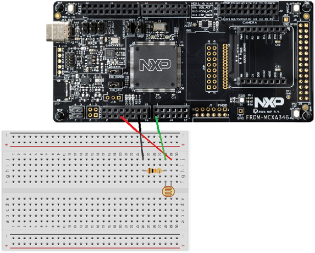
Wiring
We'll use the board's LDO_3V3 pin as the voltage source in this project. Make sure to use the correct pin. Check the Quick Start Guide leaflet which came with the board to ensure you are using the correct pin. Connect a jumper wire from the same rail as the one of the second leg of the LDR and the first leg of the 10 kΩ resistor to pin P1_14 (which we configured as the ADR input pin). Connect the rail of the second leg of the resistor a GND pin.
Conclusion
You have learned what Direct Memory Access (DMA) is and how it offloads data movement from the CPU. You now understand how microcontrollers can achieve higher sample rates while still allowing the CPU to perform useful work instead of being interrupted for every single data transfer.
You've also seen why cache memory should be avoided for DMA buffers and TCD structures: when the CPU is not involved in updating memory, cached values can become outdated and lead to inconsistent behavior.
Finally, you've learned that the compiler may optimize variables away if it believes they are never used. This can happen when variables are modified by hardware rather than by the CPU, such as in interrupt handlers. Declaring such variables as volatile ensures that the compiler always treats them as potentially changing and keeps them available in memory.