Reading LDR data of an ADC input pin with NXP FRDM MCX A346
Introduction
This project demonstrates how to use the lpadc_polling SDK example provided by NXP in the MCUXpresso IDE to tailor it to fit your project. In this case we will use a light dependent resistor (LDR) as the sensor to provide analog signals to the Analog to Digital Converter (ADC). An ADC converts analog voltage measurements on a continuous scale into a digital value, which a microcontroller can process. Physically an ADC is an electrical circuit on the microcontroller chip. As a system, an ADC is a measurement chain that samples, quantizes, and encodes analog signals into digital data, including timing, references, configuration, and error handling. These are all aspects you will come across when working with the lpadc_polling SDK example.
Thus far this SDK example is one of the simplest projects to adapt into a breadboard setup in this series. This provides the opportunity to dig a little deeper into some modifications we would like to make it a better fit for an LDR project.
Prerequisites
- MCUXpresso IDE installed
- NXP FRDM MCX A346 board
- Breadboard, 3 male jumper wires, 1 LDR, 1 10 kΩ resistor
- Documentation, especially the MCUXpresso Config Tools User's Guide (IDE) (download link)
Configuring the input pin
In the Quickstart Panel (if not visible: Window > Show View > Quickstart Panel) click "Import SDK Example(s)...". We'll select the FRDM MCX A346 board. In the Example view under: driver_examples > lpadc, we'll select lpadc_polling and click Finish.
We'll configure the input pin based on section 3.2 Example workflow of the MCUXpresso Config Tools User's Guide (IDE).
For this go to the Pins Tool: on the menu bar, click Config Tools > Pins.
Make sure you have your current project selected in the drop down menu in the Pins Tool.

In the Pins Tool, with the current project selected and BOARD_InitPins selected as Functional Group:
1. Select the ADC1:A, 12 signal in the Pins View. You can either do this by clicking into the ADC1:A, 12 cell or by checking the checkbox of pin 7 and, in the dialog, checking ADC1:A, 12.
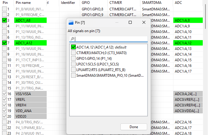
2. Click Update Code.

With only these two steps we have already configured the pin for ADC input. If we look at the pin_mux.c code (in your project folder > board), inside the BOARD_InitPins() function, you'll see pin 7 is configured as ADC1_A12.
Code
To turn this SDK example into a working breadboard setup, only a single small adjustment has to be made to the code. In app.h (in your project folder > board) change the value "8U" into "12U". This "12" is the 12 in "ADC1_A12".
So instead of:
#define DEMO_LPADC_USER_CHANNEL 8Uyou should have:
#define DEMO_LPADC_USER_CHANNEL 12UOne final adjustment, which isn't strictly necessary, but easier for seeing the result of the measurement is the following. In your main .c-file (i.e. lpadc_polling.c in your project folder > source) instead of GETCHAR(); you could write SDK_DelayAtLeastUs(500000, CLOCK_GetFreq(kCLOCK_CoreSysClk)); which may make it easier to see the change in values of the lighting. So your while super loop in int main() would look like:
...
    while (1)
    {
        SDK_DelayAtLeastUs(500000, CLOCK_GetFreq(kCLOCK_CoreSysClk));
        LPADC_DoSoftwareTrigger(DEMO_LPADC_BASE, 1U); /* 1U is trigger0 mask. */
...
You can delete or comment out this line, because with this last adjustment you don't have to press a button:
PRINTF("Please press any key to get user channel's ADC value.\r\n");Wiring
We'll use the board's LDO_3V3 pin as the voltage source in this project. Make sure to use the correct pin. Check the Quick Start Guide leaflet which came with the board to ensure you are using the correct pin. Connect a jumper wire from the same rail as the one of the second leg of the LDR and the first leg of the 10 kΩ resistor to pin P1_14 (which we configured as the ADR input pin). Connect the rail of the second leg of the resistor a GND pin.
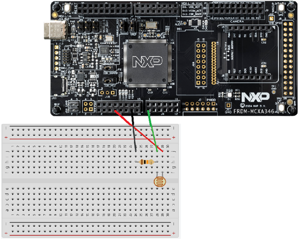
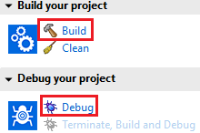
If you connect the board to your PC or laptop and build, debug, resume session, the terminal should print different values every half a second depending on changing lighting.
If the terminal tab is blank or the terminal is
Expanding our understanding of this ADC project to make some conscious decisions: breadboard setup
First we'll take a look at the breadboard setup and explain we I choose 10kΩ resistor. After that I'll explain why I want to make some changes to the SDK example.
Why a resistor in the first place?
There are two reasons to use a resistor.
1. Current limiting
An LDR is simply a resistor whose value depends on light. In bright light its resistance can drop to relatively low values. According to Ohm's law:
Current = Voltage / Resistance
a low resistance at a fixed supply voltage results in a higher current. Without a series resistor, the current through the LDR and the rest of the circuit could become much higher than intended.
Excessive current is dangerous because it increases power dissipation. Even at low voltages, high current can overheat components, damage PCB traces, and stress the protection diodes inside a microcontroller input. A series resistor limits the maximum current in the circuit, keeping the LDR, the wiring, and the microcontroller safely within their operating limits.
2. Creating a measurable voltage
A single resistor cannot produce a measurable intermediate voltage. With only one resistor between Vcc and ground, the entire supply voltage appears across that resistor. Every point on the wire after the resistor is at the same potential, so measuring between those points gives 0V. There is no "tap point" where a partial voltage exists.
To create a measurable voltage, you need two resistors in series. The supply voltage is then divided between them. The amount of voltage dropped across each resistor depends on their relative resistance values. For example, a 440Ω resistor will drop twice as much voltage as a 220Ω resistor.
By adding a fixed resistor below the LDR, you create a midpoint between the two resistors. The voltage at that midpoint depends on the ratio between the LDR and the fixed resistor. Because the LDR's resistance changes with light, the midpoint voltage changes as well - and that is the voltage the microcontroller can safely measure.
Why a 10 kΩ resistor?
The light resistance of my LDR ranges between roughly 8 and 20kΩ (at 25℃). To get the best possible voltage range from a voltage divider, you want the fixed resistor to be close to the average resistance of the LDR. In this case that average is around 14kΩ, and a standard 10kΩ resistor is the closest common value. Always check the datasheet of your own LDR to find its typical light resistance.
Earlier I mentioned that a 440Ω resistor drops twice as much voltage as a 220Ω resistor. The same principle applies here: the voltage at the midpoint of a voltage divider depends on the ratio between the two resistors. If the two values are very far apart, the divider becomes dominated by one of them, and the output voltage barely changes when the LDR changes.
For example, if the LDR averages around 14kΩ and the fixed resistor is only 1kΩ, the LDR dominates the divider and you will mostly read low voltages. If the fixed resistor is extremely large, say 1MΩ, then the fixed resistor dominates and you will mostly read high voltages.
When the resistor values differ too much, the useful voltage range becomes very small. That means you lose resolution - the ADC can only quantize a limited number of steps, and most of those steps will be compressed into a tiny part of the range.
That's why you typically choose the fixed resistor close to the average light resistance of your LDR: it gives the widest, most useful voltage swing for the ADC.
Expanding our understanding of this ADC project to make some conscious changes to the SDK example: the code
#if, #else, #endif syntax
These directives belong to the C preprocessor. They are evaluated before the compiler runs. The preprocessor determines which parts of the source code are included or excluded, and only the included code is passed on to the compiler.
#if (defined(DEMO_LPADC_USE_HIGH_RESOLUTION) && DEMO_LPADC_USE_HIGH_RESOLUTION)
first checks whether the macro
DEMO_LPADC_USE_HIGH_RESOLUTION is defined, and
then whether its value is non-zero (true).
If both conditions are true, the following code is included:
const uint32_t g_LpadcFullRange   = 65536U;
const uint32_t g_LpadcResultShift = 0U;
Otherwise, the #else block is included instead:
const uint32_t g_LpadcFullRange   = 4096U;
const uint32_t g_LpadcResultShift = 3U;
#endif marks the end of this conditional compilation block.
Setting DEMO_LPADC_USE_HIGH_RESOLUTION to false
For our project we set the value of DEMO_LPADC_USE_HIGH_RESOLUTION to false (defined in app.h under the board folder):
#define DEMO_LPADC_USE_HIGH_RESOLUTION falseThis means that g_LpadcFullRange will be set to 4096U. Here's why that choice makes sense.
As mentioned in the introduction, an ADC is a measurement chain that samples, quantizes, and encodes analog signals. Analog values exist on a smooth, continuous scale, but a digital system can only store discrete values. Quantization is the process of mapping a continuous analog value to one of a limited number of digital steps.
The number of bits used for this mapping determines the resolution. In our case, the high resolution mode uses 16 bits (216 = 65536 steps), while the low resolution mode uses 12 bits (212 = 4096 steps). Even 12-bit resolution already provides 4096 discrete levels, which is more than enough for most sensors.
This matters because higher resolution is not free. A 16-bit conversion typically consumes more energy than a 12-bit conversion, which is important in battery powered applications or large scale production where every microamp matters. More importantly, the sensor itself must justify the higher resolution. LDRs do not: they are strongly affected by temperature, aging, and noise, and their output is inherently imprecise. Using a 16-bit ADC on such a sensor does not produce more meaningful information - it only increases energy consumption without improving measurement quality.
For that reason, the 12-bit mode (4096 steps) is the most sensible choice for an LDR-based measurement.
powerLevelMode
mLpadcConfigStruct.powerLevelMode = kLPADC_PowerLevelAlt4;we will use:
mLpadcConfigStruct.powerLevelMode = kLPADC_PowerLevelAlt2;The LPADC supports four power levels (Alt1, Alt2, Alt3, Alt4). These levels control how much power the ADC consumes, how fast it can operate, and the resulting accuracy, noise performance, and achievable resolution. Higher power levels provide better signal-to-noise ratio and are typically required for 16-bit conversions.
In our LDR setup, Alt2 is a sensible choice. LDRs are relatively noisy and imprecise sensors, so using a high power, high resolution ADC mode would not yield more meaningful information. Alt2 provides a good balance between energy consumption and practical measurement accuracy.
Conclusion
You have learned how to adapt the lpadc_polling SDK example to build a breadboard setup using a light dependent resistor and the LPADC. You now know how to choose an appropriate resistor for the voltage-divider circuit, and you've been introduced to C preprocessor directives. Finally, you've seen how to make an informed decision about ADC quantization resolution and the corresponding power level mode when working with an LDR.
In a future article, I will explore using interrupts in combination with the ADC which will reduce energy consumption even further. Keep an eye on this website for more tutorials on the NXP FRDM MCX A346.