Enable IIS3DWB accelerometer and read temperature data from a NXP FRDM-MCXN947 controller using SPI
Introduction
In this article we'll learn how to enable the IIS3DWB accelerometer and read temperature data. We'll use the NXP FRDM-MCXN947 as the controller and SPI as the communication protocol. We'll use type casting and shifting bits to turn two uint8_t bytes into a single int16_t byte, which we'll then turn into a float.
First we're going to enable the accelerometer so it can perform temperature measurements. We'll need to send a write command from the MCXN947 to enable the IIS3DWB. Then we can send requests to read the temperature data. We'll see that the temperature data is stored at two separate register addresses on the IIS3DWB. On the MCXN947 we're going to convert uint8_t data into int16_t data through type casting. Finally we'll convert the data again into a float and ensure the value represents the temperature in degrees Celsius.
Prerequisites
- MCUXpresso IDE installed
- NXP FRDM-MCXN947 board
- Breadboard, 7 male jumper wires
- STMicroelectronics STEVAL-MKI208V1K evaluation board (STEVAL-MKIGIBV2 adapter board, cable and STEVAL-MKI208V1 board embedding the IIS3DWB sensor)
- IIS3DWB datasheet (download link)
Configuring your project
In the MCUXpresso IDE: create a new C Project.
On the Configure the project page, give the project an appropriate name of your own choosing (i.e. "MCXN947_iis3dwb_spi_temperature_demo").
Still on the Configure the project page under Components, expand Drivers > Device > SDK Drivers > select these three drivers: flexspi; inputmux; inputmux_connections.
Click Finish.
Configuring the pins
On the menu bar, click Config Tools > Pins.
Make sure you have your current project selected in the drop down menu in the Pins Tool.
Click the Functional Group Properties button.
In the Functional Group Properties dialog box click the Add a new functional group button.
Change the name to BOARD_InitPins and click OK.
Now you should have BOARD_InitPins selected as the functional group you are configuring using the Pins Tool.
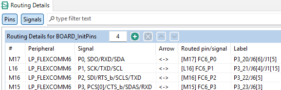
In the Pins View select the pin labeled P3_20 etc., in the dialog box, scroll down and select LP_FLEXCOMM6 etc. Click done.
Repeat this for pins P3_21, P3_22 and P3_23.
The Routing Details View should look like this:
Click Update Code. Click OK in the dialog box.
Printing floats in the terminal of the MCUXpresso IDE
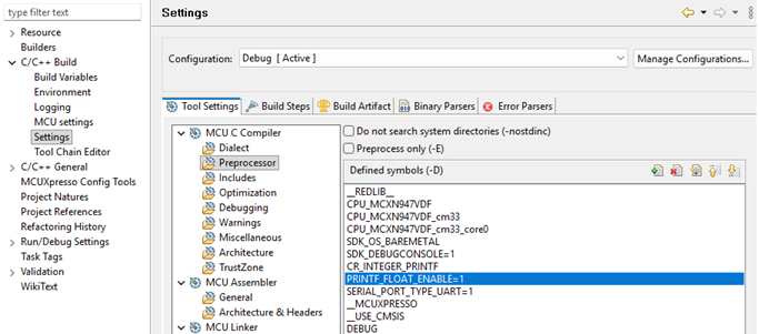
To be able to print float values in the terminal of MCUXpresso you need to enable that functionality in the IDE. Click Project > Properties > C/C++ Build > Settings > MCU C Compiler > Preprocessor and make sure you have the correct settings: PRINTF_FLOAT_ENABLE=1. Click Apply and Close.
Code
Rename the c file holding your main function (i.e. "MCXN947_iis3dwb_spi_enable_accelerometer_demo_main.c").
Right click on your source folder > New > Source File. Name the file "iis3dwb_spi.c". Click Finish.
Right click on your source folder > New > Header File. Name the file "iis3dwb_spi.h". Click Finish.
Right click on your source folder > New > Source File. Name the file "spi.c". Click Finish.
Right click on your source folder > New > Header File. Name the file "spi.h". Click Finish.
MCXN947_iis3dwb_spi_enable_accelerometer_demo_main.c:
#include <stdio.h>
#include "board.h"
#include "peripherals.h"
#include "pin_mux.h"
#include "clock_config.h"
#include "fsl_debug_console.h"

#include "fsl_common.h"
#include <string.h>
#include <math.h>
#include "fsl_lpspi.h"
#include "iis3dwb_spi.h"
#include "fsl_port.h"
#include "fsl_clock.h"

#include <stdint.h>

#define IIS3DWB_BOOT_TIME_MS   20

int main(void) {

    BOARD_InitBootPins();
    BOARD_InitBootClocks();
    BOARD_InitBootPeripherals();
    BOARD_InitDebugConsole();

    CLOCK_EnableClock(kCLOCK_LPFlexComm6);
    CLOCK_SetClkDiv(kCLOCK_DivFlexcom6Clk, 1U);
    CLOCK_AttachClk(kFRO12M_to_FLEXCOMM6);

    lpspi_master_config_t masterConfig;
    LPSPI_MasterGetDefaultConfig(&masterConfig);

    masterConfig.baudRate = 1000000U;
    masterConfig.bitsPerFrame = 8U;
    masterConfig.cpol = kLPSPI_ClockPolarityActiveHigh;
    masterConfig.cpha = kLPSPI_ClockPhaseFirstEdge;

    LPSPI_MasterInit(LPSPI6, &masterConfig, CLOCK_GetLPFlexCommClkFreq(6U));

    SDK_DelayAtLeastUs(IIS3DWB_BOOT_TIME_MS * 1000, CLOCK_GetFreq(kCLOCK_CoreSysClk));

    uint8_t whoamiid = 0;
    if (iis3dwb_whoami(&whoamiid))
    {
        PRINTF("WHO_AM_I = 0x%02X\r\n", whoamiid);
    }
    else
    {
        PRINTF("WHO_AM_I READ FAILED\n");
    }

    if (!iis3dwb_enable_accelerometer())
    {
        PRINTF("ENABLE_ACCELEROMETER WRITE FAILED\n");
    }

    SDK_DelayAtLeastUs(IIS3DWB_BOOT_TIME_MS * 1000, CLOCK_GetFreq(kCLOCK_CoreSysClk));

    while (1)
    {
        uint8_t temperature_high = 0;
        if (!iis3dwb_temperature_h(&temperature_high))
        {
            PRINTF("TEMPERATURE_HIGH READ FAILED\n");
        }

        uint8_t temperature_low = 0;
        if (!iis3dwb_temperature_l(&temperature_low))
        {
            PRINTF("TEMPERATURE_LOW READ FAILED\n");
        }

        /*
         * These were separate reads for the high bits and low bits.
         * They very likely belong to two different measurements.
         * The 16 bit temperature value is therefore very likely not an actual single measurement.
         * It is very likely a value based on two separate measurements.
         * This code is merely intended to demonstrate type casting and bit shifting.
         * It demonstrates how to convert two uint8_t values into a single int16_t value.
         */
        int16_t raw_temperature = ((int16_t)temperature_high << 8) | temperature_low;
        float temperature_celsius = ((float)raw_temperature / 256.0f) + 25.0f;
        PRINTF("Temperature in degrees Celsius = %f\r\n", temperature_celsius);

        SDK_DelayAtLeastUs(500000, CLOCK_GetFreq(kCLOCK_CoreSysClk));
    }
}
iis3dwb_spi.c
#include "iis3dwb_spi.h"
#include "spi.h"
#include <stdio.h>
#include <string.h>
#include "fsl_debug_console.h"

#define IIS3DWB_SPI_WRITE_MASK            0x7FU // 01111111
#define IIS3DWB_SPI_READ_BIT              0x80U // 10000000

// See table 8 of the IIS3DWB datasheet for the register address map
#define IIS3DWB_WHO_AM_I_REG              0x0FU
#define IIS3DWB_CTRL1_XL_REG              0x10U
#define IIS3DWB_OUT_TEMP_H_REG            0x21U
#define IIS3DWB_OUT_TEMP_L_REG            0x20U

bool iis3dwb_write_reg(uint8_t reg, uint8_t value)
{
    uint8_t tx[2] = { reg & IIS3DWB_SPI_WRITE_MASK, value };
    uint8_t rx[2] = { 0 };

    if (!spi_transfer(tx, rx, 2))
    {
        return false;
    }

    return true;
}

bool iis3dwb_read_reg(uint8_t reg, uint8_t *value)
{
    uint8_t tx[2] = { reg | IIS3DWB_SPI_READ_BIT, 0x00 };
    uint8_t rx[2] = { 0 };

    if (!spi_transfer(tx, rx, 2))
    {
        return false;
    }

    *value = rx[1];
    return true;
}

bool iis3dwb_whoami(uint8_t *id)
{
    return iis3dwb_read_reg(IIS3DWB_WHO_AM_I_REG, id);
}

bool iis3dwb_enable_accelerometer()
{
    /*
     * See table 28 and 29 of the IIS3DWB datasheet:
     * The 3 leftmost bits of CTRL1_XL register must be 101 to enable the accelerometer.
     * 0xA0 is hex for binary 10100000.
     * The other bits of that register are 0 by default. Other settings require different commands.
     * A real function would take into account these other settings,
     * like using OR operators with other macros representing the configuration bits for other functionalities.
     * This will be discussed in the next article.
     * Reminder: just writing 0xA0 here is not a good practice.
     * This code is intended to demonstrate that 10100000 is written to an IIS3DWB register address.
     */
    return iis3dwb_write_reg(IIS3DWB_CTRL1_XL_REG, 0xA0); //0xA0 is 10100000 in binary
}

bool iis3dwb_temperature_h(uint8_t *id)
{
    return iis3dwb_read_reg(IIS3DWB_OUT_TEMP_H_REG, id);
}

bool iis3dwb_temperature_l(uint8_t *id)
{
    return iis3dwb_read_reg(IIS3DWB_OUT_TEMP_L_REG, id);
}
iis3dwb_spi.h
#pragma once
#include <stdint.h>
#include <stdbool.h>

bool iis3dwb_write_reg(uint8_t reg, uint8_t value);
bool iis3dwb_read_reg(uint8_t reg, uint8_t *value);
bool iis3dwb_whoami(uint8_t *id);
bool iis3dwb_enable_accelerometer();
bool iis3dwb_temperature_h(uint8_t *id);
bool iis3dwb_temperature_l(uint8_t *id);
spi.c
#include "fsl_lpspi.h"
#include "fsl_device_registers.h"
#include <stdint.h>
#include <stdbool.h>
#include <stdio.h>
#include <string.h>
#include "fsl_gpio.h"

bool spi_transfer(const uint8_t *tx, uint8_t *rx, size_t len)
{
    lpspi_transfer_t xfer = {0};

    xfer.txData = (uint8_t *)tx;
    xfer.rxData = rx;
    xfer.dataSize = len;
    xfer.configFlags = kLPSPI_MasterPcs0 | kLPSPI_MasterPcsContinuous;

    status_t result = LPSPI_MasterTransferBlocking(LPSPI6, &xfer);

    return result == kStatus_Success;
}
spi.h
#pragma once
#include <stdint.h>
#include <stdbool.h>

bool spi_transfer(const uint8_t *tx, uint8_t *rx, size_t len);
Wiring
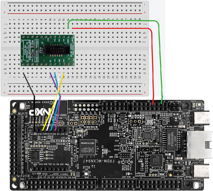
This picture omits the cable and STEVAL-MKI208V1 board. Don't forget to connect the cable between the STEVAL-MKI208V1 board and the STEVAL-MKIGIBV2 adapter board!
| STEVAL-MKI208V1 pin number | STEVAL-MKI208V1 pin label | FRDM-MCXN947 pin label | FRDM-MCXN947 board location |
|---|---|---|---|
| 22 | SDO | P3_22 | J6-5 |
| 21 | SDA | P3_20 | J6-6 |
| 20 | SCL | P3_21 | J6-4 |
| 19 | CS | P3_23 | J6-3 |
| 13 | GND | GND | |
| 1 | VDD | P3V3 | |
| 2 | VDDIO | P3V3 |
Debugging the project
Click Build.
Click Debug: leave all default settings as they are.
Click the terminal. Open a new terminal if needed.
Click the Resume button at the top of the window.
The terminal should print something with roughly the sensor's environment temperature values:
WHO_AM_I = 0x7B
Temperature in degrees Celsius = 22.234375
Temperature in degrees Celsius = 22.312500
Temperature in degrees Celsius = 22.292969
Temperature in degrees Celsius = 22.269531
...etc.
How to enable the IIS3DWB accelerometer
Paragraph 9.11 of the IIS3DWB datasheet provides a description of accelerometer control register 1. The three leftmost bits enable the accelerometer. Their default value is 000 (power-down). To enable the accelerometer these bits must be set to 101.
In the last article we sent a read command down the MOSI line (controller out, target in). Our transmitter array (uint8_t tx[2]) held two elements. One element combined the read bit and register. The second element was set to zero.
This time we're going to send a write command down the MOSI line. Because we're sending a write command, the second element of our transmitter array will hold the value we want to write. The first element combines the write bit (a zero) and the register address of accelerometer control register 1.
Since we'll send a uint8_t value down the MOSI line, this means we can send a uint8_t value equivalent of binary 10100000. This works fine for this tutorial, but please keep in mind that the other bits configure the full scale selection and can enable low-pass filter 2. In an industrial use case you'll very likely choose a different configuration (like 10100110: ±16 g full scale and low-pass filter 2 enabled).
The values for our transmitter array
In the last article we learned how to create a read function for our IIS3DWB driver. If we read paragraph 3.2 of the IIS3DWB datasheet again, we can read: "bit 0: RW bit. When 0, the data DI(7:0) is written into the device. When 1, the data DO(7:0) from the device is read." So in our iis3dwb_write_reg() function we want to make sure the first bit we're going to send will be a 0.
Paragraph 3.2 of the IIS3DWB datasheet continues: "bit 1-7: address AD(6:0). This is the address field of the indexed register. bit 8-15: data DI(7:0) (write mode). This is the data that is written into the device (MSb first)." "MSb" stands for "Most Significant bit", the bit which represents the highest numerical value. In our case that's the leftmost bit.
The register address of Accelerometer control register 1 (CTRL1_XL) is 00010000 in binary and 10 in hexadecimal (0x10 in C hexadecimal notation). Since we want to send a write command we have to make sure the first leftmost bit will be zero, because that is the RW bit which has to be 0 for writing.
In our case the register address already starts with a zero and so do all the registers on the IIS3DWB. Ensuring the first is 0 may look redundant, but if we imagine we'll be working with many different sensors in the future from various manufacturers, we may need to remind ourselves we need to adapt our write function in those use cases. We do this by using a bitwise AND operation, which I'll explain in the next paragraph.
To summarize, our transmitter array (uint8_t tx[2]) is going to hold two elements (00010000, 10100000 in binary) where 00010000 is a write command for register 00010000, and 10100000 is the value written to the device as that register's new value enabling the accelerometer while maintaining the default values for the configuration of full scale selection and low-pass filter 2 (assuming these bits are in their default settings before writing).
Using a bitwise AND operation to ensure we're sending a write command
We want to combine two uint8_t values while ensure the leftmost bit will always be 0. We're going to achieve this by applying a bitwise AND operation. A bitwise AND operator & compares the bits at identical positions (the same bit numbers) and outputs a 1 only if both bits are 1. If we have two bytes and the leftmost bit of either is 0, the leftmost bit of the newly created byte will be 0, which is exactly what we want in our situation.
We need however take into account the other 7 bits of the newly created uint8_t variable. In our example the binary value of our variable should become 00010000. If we would combine 00010000 (the register address) with 00000000 and apply a bitwise AND operation, the resulting byte will be 00000000 and our write command will fail to communicate the register we want to write to. To ensure all other bits retain their value (if their value is 1), both bits at their identical position must be 1. Taken together we want to take the bytes 00010000 and 01111111, apply a bitwise AND operation, and we yield 00010000 as our command where the leftmost bit is guaranteed to be 0. 01111111 is a bitmask, because it acts as a mask or stencil which is put over the input data.
  IIS3DWB_SPI_WRITE_MASK:    0  1  1  1  1  1  1  1   (0x7F)
& IIS3DWB_CTRL1_XL_REG:      0  0  0  1  0  0  0  0   (0x10)
= ----------------------------------------------------------
  Resulting Byte:            0  0  0  1  0  0  0  0   (0x10)
In our iis3dwb_enable_accelerometer() function we pass the register address of accelerometer control register 1, which is 10 in hexadecimal (see table 8 of the IIS3DWB datasheet), by using the IIS3DWB_CTRL1_XL_REG macro with the value 0x10 as an argument. In our iis3dwb_write_reg(uint8_t reg, uint8_t value) function this value is held by our reg parameter. Our reg & IIS3DWB_SPI_WRITE_MASK operation performs the bitwise AND operation described above. This creates the first element of our transmitter array uint8_t tx[2].
As mentioned in the two sections above we want the second element to hold the value 10100000 in binary, since this is the command to enable the accelerometer. 0xA0 is the C notation hexadecimal for 10100000, which is why we pass it as the second argument. To someone who isn't familiar with the project, it is probably unclear where this 0xA0 value comes from. That's why, in practice, we want to replace this value by a macro as well, like ACCELEROMETER_ENABLE.
Type casting and bit shifting
In this project we want to read the temperature measurements from the IIS3DWB. Paragraph 9.22 of the IIS3DWB datasheet informs us that the temperature data output is spread across two registers. So we'll read two uint8_t values and have to convert these into a single int16_t value.
For the simplicity of this tutorial we'll execute two independent read commands to collect the two values. Since the IIS3DWB is very fast, using the setup in this tutorial will mean that the two values we collect, won't be part of the same measurement. By the time we have finished the first read and start executing the second read, the data in the other register has already been overwritten. This is an issue we'll deal with in the next article. For now, we'll focus on converting two values into another type.
To convert a single uint8_t value to an int16_t we can declare an int16_t and initialize it by placing parentheses around the desired type followed by the variable we're converting:
uint8_t temperature_high = 0;
int16_t raw_temperature = (int16_t)temperature_high;
In our project the temperature_high data should represent the most significant 8 bits of the ultimate temperature value. To achieve this, we want to shift the temperature_high bits 8 positions to the left. To do this, we simply take bits we want to shift, place << bit shift symbols and the number of positions we want the bits to shift.
uint8_t myint = 1;
uint8_t shiftedint = myint << 2;
PRINTF("My int after bit shift = %d\r\n", shiftedint);
//My int after bit shift = 4
//00000001 shifted 2 positions to the left to create 00000100

uint8_t myotherint = 0x01;
uint8_t othershiftedint = myotherint << 3;
PRINTF("My other int after bit shift = 0x%02X\r\n", othershiftedint);
//My other int after bit shift = 0x 8
//00000001 shifted 3 positions to the left to create 00001000
As we can we see in the main() function, after we have shifted the temperature_high bits 8 position to the left, we can perform a bitwise OR | operation to place the temperature_low bits at the position of the 8 least significant bits of the int16_t byte.
Paragraph 2.3 of the IIS3DWB tells us the temperature sensitivity is 256 bits per degree Celsius and if the output of the temperature sensor is 0 LSB (least significant bit), this typically means the sensor measured 25 degrees Celsius. This is why we have to divide the raw temperature by 256 and add 25 to convert the raw sensor data into the correct float value.
Conclusion
You have learned how to create write commands and how to perform bitwise AND operations to configure the IIS3DWB sensor from an NXP FRDM-MCXN947 controller.
You have also learned about type casting and bit shifting so you can convert one or more uint8_t variables into a int16_t variable.
In the next article I will explore how to read actual accelerometer data from the IIS3DWB. Keep an eye on this website for more tutorials on the NXP FRDM-MCXN947.