STEVAL-MKI208V1K and NXP FRDM-MCXN947 SPI WHO_AM_I sanity check
Introduction
This article will serve as a guide for an SPI (Serial Peripheral Interface communication protocol) WHO_AM_I sanity check for the STMicroelectronics STEVAL-MKI208V1K kit for the IIS3DWB sensor and a NXP FRDM-MCXN947 evaluation board.
In this project we will simply program the FRDM-MCXN947 to read the WHO_AM_I register value of the IIS3DWB sensor and print it to MCUXpresso IDE's terminal using SPI as the serial communication protocol.
Prerequisites
- MCUXpresso IDE installed
- NXP FRDM-MCXN947 board
- Breadboard, 7 male jumper wires
- STMicroelectronics STEVAL-MKI208V1K evaluation board (STEVAL-MKIGIBV2 adapter board, cable and STEVAL-MKI208V1 board embedding the IIS3DWB sensor)
- IIS3DWB datasheet (download link)
Configuring your project
In the MCUXpresso IDE: create a new C Project.
On the Configure the project page, give the project an appropriate name of your own choosing (i.e. "MCXN947_iis3dwb_whoami_demo").
Still on the Configure the project page under Components, expand Drivers > Device > SDK Drivers > select these three drivers: flexspi; inputmux; inputmux_connections.
Click Finish.
Configuring the pins
On the menu bar, click Config Tools > Pins.
Make sure you have your current project selected in the drop down menu in the Pins Tool.
Click the Functional Group Properties button.
In the Functional Group Properties dialog box click the Add a new functional group button.
Change the name to BOARD_InitPins and click OK.
Now you should have BOARD_InitPins selected as the functional group you are configuring using the Pins Tool.
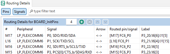
In the Pins View select the pin labeled P3_20 etc., in the dialog box, scroll down and select LP_FLEXCOMM6 etc. Click done.
Repeat this for pins P3_21, P3_22 and P3_23.
The Routing Details View should look like this:
Click Update Code. Click OK in the dialog box.
Code
Rename the c file holding your main function (i.e. "MCXN947_iis3dwb_spi_whoami_demo_main.c").
Right click on your source folder > New > Source File. Name the file "iis3dwb_spi.c". Click Finish.
Right click on your source folder > New > Header File. Name the file "iis3dwb_spi.h". Click Finish.
Right click on your source folder > New > Source File. Name the file "spi.c". Click Finish.
Right click on your source folder > New > Header File. Name the file "spi.h". Click Finish.
MCXN947_iis3dwb_spi_whoami_demo_main.c:
#include <stdio.h>
#include "board.h"
#include "peripherals.h"
#include "pin_mux.h"
#include "clock_config.h"
#include "fsl_debug_console.h"

#include "fsl_common.h"
#include <string.h>
#include <math.h>
#include "fsl_lpspi.h"
#include "iis3dwb_spi.h"
#include "fsl_port.h"
#include "fsl_clock.h"

#define IIS3DWB_BOOT_TIME_MS   20

int main(void)
{
    BOARD_InitBootPins();
    BOARD_InitBootClocks();
    BOARD_InitBootPeripherals();
    BOARD_InitDebugConsole();

    CLOCK_EnableClock(kCLOCK_LPFlexComm6);
    CLOCK_SetClkDiv(kCLOCK_DivFlexcom6Clk, 1U);
    CLOCK_AttachClk(kFRO12M_to_FLEXCOMM6);

    lpspi_master_config_t masterConfig;
    LPSPI_MasterGetDefaultConfig(&masterConfig);
    masterConfig.baudRate = 1000000U;
    masterConfig.bitsPerFrame = 8U;
    masterConfig.cpol = kLPSPI_ClockPolarityActiveHigh;
    masterConfig.cpha = kLPSPI_ClockPhaseFirstEdge;

    LPSPI_MasterInit(LPSPI6, &masterConfig, CLOCK_GetLPFlexCommClkFreq(6U));

    SDK_DelayAtLeastUs(IIS3DWB_BOOT_TIME_MS * 1000, CLOCK_GetFreq(kCLOCK_CoreSysClk));

    uint8_t whoami = 0;
    if (iis3dwb_whoami(&whoami))
    {
        PRINTF("Initial WHO_AM_I = 0x%02X\r\n", whoami);
    }
    else
    {
        PRINTF("READ FAILED\n");
    }

    while (1) {
        uint8_t id = 0;
        iis3dwb_whoami(&id);
        PRINTF("WHO_AM_I = 0x%02X\r\n", id);

        SDK_DelayAtLeastUs(500000, CLOCK_GetFreq(kCLOCK_CoreSysClk));
    }
}
iis3dwb_spi.c
#include "iis3dwb_spi.h"
#include "spi.h"
#include <stdio.h>
#include <string.h>
#include "fsl_debug_console.h"

#define IIS3DWB_WHO_AM_I_REG     0x0FU
#define SPI_READ_BIT             0x80U

bool iis3dwb_read_reg(uint8_t reg, uint8_t *value)
{
    uint8_t tx[2] = { reg | SPI_READ_BIT, 0x00 };
    uint8_t rx[2] = { 0 };

    if (!spi_transfer(tx, rx, 2))
    {
        return false;
    }

    *value = rx[1];
    return true;
}

bool iis3dwb_whoami(uint8_t *id)
{
    return iis3dwb_read_reg(IIS3DWB_WHO_AM_I_REG, id);
}
iis3dwb_spi.h
#pragma once
#include <stdint.h>
#include <stdbool.h>

bool iis3dwb_read_reg(uint8_t reg, uint8_t *value);
bool iis3dwb_whoami(uint8_t *id);
spi.c
#include "fsl_lpspi.h"
#include "fsl_device_registers.h"
#include <stdint.h>
#include <stdbool.h>
#include <stdio.h>
#include <string.h>
#include "fsl_gpio.h"

bool spi_transfer(const uint8_t *tx, uint8_t *rx, size_t len)
{
    lpspi_transfer_t xfer = {0};

    xfer.txData = (uint8_t *)tx;
    xfer.rxData = rx;
    xfer.dataSize = len;
    xfer.configFlags = kLPSPI_MasterPcs0 | kLPSPI_MasterPcsContinuous;

    status_t result = LPSPI_MasterTransferBlocking(LPSPI6, &xfer);

    return result == kStatus_Success;
}
spi.h
#pragma once
#include <stdint.h>
#include <stdbool.h>

bool spi_transfer(const uint8_t *tx, uint8_t *rx, size_t len);
Wiring
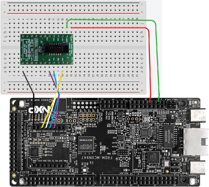
This picture omits the cable and STEVAL-MKI208V1 board. Don't forget to connect the cable between the STEVAL-MKI208V1 board and the STEVAL-MKIGIBV2 adapter board!
| STEVAL-MKI208V1 pin number | STEVAL-MKI208V1 pin label | FRDM-MCXN947 pin label | FRDM-MCXN947 board location |
|---|---|---|---|
| 22 | SDO | P3_22 | J6-5 |
| 21 | SDA | P3_20 | J6-6 |
| 20 | SCL | P3_21 | J6-4 |
| 19 | CS | P3_23 | J6-3 |
| 13 | GND | GND | |
| 1 | VDD | P3V3 | |
| 2 | VDDIO | P3V3 |
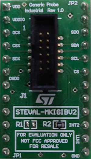
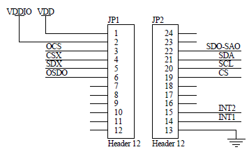
The STEVAL-MKIGIBV2 adapter board is a multipurpose adapter board which is also used for other sensors like the LSM6DSOX. The STEVAL-MKIGIBV2 adapter board also has pins labeled OCS, CSX, SDX and OSDO, but we won't use those pins for the IIS3DWB sensor. These pins are however used for sensors like the LSM6DSOX, which also uses the same LGA-14L package type as the IIS3DWB. This is probably done by STMicroelectronics for cost efficiency reasons.
Debugging the project
Click Build.
Click Debug: leave all default settings as they are.
Click the terminal. Open a new terminal if needed.
Click the Resume button at the top of the window.
The terminal should print:
Initial WHO_AM_I = 0x7B
WHO_AM_I = 0x7B
WHO_AM_I = 0x7B
WHO_AM_I = 0x7B
...etc.
Code explanation
WHO_AM_I register
For this WHO_AM_I sanity check we want to read the value the value of the WHO_AM_I register on the IIS3DWB. If we look at table 8 of the IIS3DWB datasheet we see the WHO_AM_I register address is 0F (hexadecimal value). In the code of our iis3dwb_spi.c file we define a IIS3DWB_ WHO_AM_I macro with a value of 0x0FU (the U ensures it is an unsigned integer).
Table 8 of the IIS3DWB datasheet tells us that the value of the WHO_AM_I register of the IIS3DWB is 01111011, which is 7B in hexadecimal. The terminal will print this value in hexadecimal along with the rest of the PRINTF command. Only if the terminal consistently prints 7B, we know our hardware and software is set up correctly.
IIS3DWB SPI bus interface
So we want to read the value of the WHO_AM_I register of the IIS3DWB. If we read paragraph 3.2 of the IIS3DWB we can read: "bit 0: RW bit. When 0, the data DI(7:0) is written into the device. When 1, the data DO(7:0) from the device is read." Since we want to read, we need to make sure the first bit we send has the value 1.
The IIS3DWB datasheet continues: "bit 1-7: address AD(6:0). This is the address field of the indexed register." Since we want to read register address 00001111, our complete 8-bit value we need to send will have to be 10001111. We could hardcode its hexadecimal equivalent (8F), but in future we likely want to read more registers than just the WHO_AM_I register. To facilitate this we'll use a bitwise OR operation to combine any register address with an 8-bit integer to create a read register command for the IIS3DWB.
Bitwise OR operation
A bitwise (inclusive) OR operator ("|") compares the bits at identical positions (the same bit numbers) and outputs a 1 if either of the input bits is 1, or if both are 1. In our case we want to combine the register address value 00001111 (hexadecimal: 0F) and 10000000 (hexadecimal: 80) to get 10001111, a single 8-bit integer which acts as a read command (left bit is 1) for register 00001111.
  SPI_READ_BIT:              1  0  0  0  0  0  0  0   (0x80)
| IIS3DWB_WHO_AM_I_REG:      0  0  0  0  1  1  1  1   (0x0F)
= ----------------------------------------------------------
  Resulting Byte:            1  0  0  0  1  1  1  1   (0x8F)
In our code of the iis3dwb_spi.c file we use the variable name and the macro: reg | SPI_READ_BIT.
The value of reg is 0x0F (00001111) and the value of SPI_READ_BIT is 0x80 (10000000). By using variable names instead of hardcoded addresses we use the iis3dwb_read_reg() function for reading multiple registers. All we have to do is create similar functions like iis3dwb_whoami().
Passing two integer arrays with two elements
uint8_t tx[2] = { reg | SPI_READ_BIT, 0x00 };
uint8_t rx[2] = { 0 };
If we look at the code of the iis3dwb_spi.c file we can see we're creating two integer arrays (uint8_t integers). While we may be used to see integer arrays like this: { 2, 3, 5, 7, 11 }, in our case one integer is created by the bitwise operation reg | SPI_READ_BIT as discussed above (10001111 in binary is just 143 as a decimal integer). 0x00 is C notation for 0 in binary. { 0 } tells the compiler to allocate the 2 bytes of memory and fill it with zeros. So, why all these zeros?
A feature of the SPI communication protocol is its full duplex mechanism: one bit out, one bit in. For every single bit the controller pushes out on the MOSI wire (P3_20 to SDA), the target pushes one bit back on the MISO wire (SDO to P3_22) at the exact same moment.
uint8_t tx[2] = { reg | SPI_READ_BIT, 0x00 }; holds the two bytes which will be sent down the MOSI wire. The first element encodes our read command. The second element just creates 0 value bits with which the IIS3DWB will do nothing (SPI forces us to send something while the target pushes out the requested data, so we just send zeros from the controller). While these bits are read by the IIS3DWB, the IIS3DWB pushes the requested WHO_AM_I data down the MISO wire.
uint8_t rx[2] = { 0 }; merely serves as reservation of memory. It creates two empty memory fields. Once the SPI transfer starts, these memory fields will be filled with data. The first field, element 0, will hold garbage data (zeros, ones, or the read command echoed back). The second field, element 1, will store our desired data. *value = rx[1]; tells the compiler to store the desired data (rx[1]) at the memory address held by value. In the function definition, the asterisk (*) creates a pointer variable. This is a special type of variable that holds a memory address instead of a standard number, a concept I will explore in a later article.
Conclusion
You have learned how to execute a WHO_AM_I sanity check STEVAL-MKI208V1K and NXP FRDM-MCXN947 using the SPI communication protocol.
You have also learned to create read commands to send to target using SPI. Later we can expand this knowledge to write commands as well.
You have learned how to a bitwise OR operation to create commands in such a way so you can reuse functions in your to create more commands later.