Pull-up Resistors and Debounce Demo with NXP FRDM MCX A346
Introduction
This project demonstrates how to enable pull-up resistors using the Pins Tool of the MCUXpresso IDE for the NXP FRDM MCX A346 development board. This project also demonstrates a simple debounce after a button press.
An important note about this demo is that it uses polling in the main function for reading the input pin values. Generally, this is not a good practice. In a small project like this, it is unlikely that problems arise as a result. Polling consumes CPU cycles continuously, which reduces the time available for other tasks and increases system latency, which can become a problem in larger projects. Interrupt-driven GPIO handling avoids this by reacting only when an event occurs. In a later project I will use GPIO Input Interrupt, which is the correct way for handling GPIO Input. GPIO Input Interrupt, for example, offers the possibility to prioritize certain tasks over tasks that are currently running. That's important to consider, since this enables you prioritize an interrupt over other tasks. The ARM Cortex M33 core (the CPU core inside the microcontroller) includes the Nested Vectored Interrupt Controller (NVIC), which supports configurable interrupt priorities and preemption. This allows critical events, such as an emergency stop button press, to interrupt lower priority tasks immediately.
This is an intermediate step to demonstrate how to use pull-up resistors for dealing with floating pins due to Electromagnetic Interference (EMI). If GPIO_PinRead() values swing between 0 and 1, without a button being pressed, inputs are susceptible to noise, including EMI, and therefore may read unpredictable values. This issue can be tackled by enabling a pull-up (or pull-down) resistor for your input pin.
Another issue you may have to deal with in case of button presses is "bouncing". This is the case if a button is pressed once, but the due to inherent mechanical properties of the button and electrical noise GPIO_PinRead() values swing between 0 and 1 for a couple of milliseconds. While there may also be mechanical solutions for mitigation of this problem, this demo focuses on a software solution called a "debounce".
Prerequisites
- MCUXpresso IDE installed
- NXP FRDM MCX A346 board
- Breadboard, breadboard button, 2 male jumper wires
- Documentation, especially the MCUXpresso Config Tools User's Guide (IDE) (download link) and API documentation
Configuring the input pin to enable the pull-up resistor
Create a new C Project.
On the menu bar, click Config Tools > Pins.
Make sure you have your current project selected in the drop down menu in the Pins Tool.

Since there already is a functional group for buttons by default, we can simply select that group in the dropdown menu to select BOARD_InitBUTTONsPins as the functional group to which we'll add our input pin configuration.

From here we can follow along with the documentation in the MCUXpresso Config Tools User's Guide (IDE) at section 3.2 Example workflow, tailored to our setup. So part of the text below follows the documentation's text almost exactly.
In this example, one pin (GPIO3:GPIO,9) is configured.
1. In the Pins view, select the GPIO3:GPIO,9 signal. For it, you can click into the cells to make it 'green'.

2. In the Routing Details view, select the Input direction for the GPIO3:GPIO,9 signal.
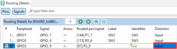
3. You'll notice warning signs. To address these warnings create an Identifier in the Pins View for the GPIO3:GPIO,9 signal. We'll create the value "MY_INPUT_P3_9" as identifier.

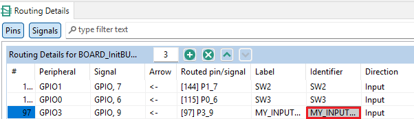
4. Next we set the identifier for the pin in the Routing Details View.
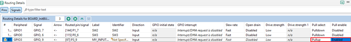
5. Now we set the pull select to pull-up in the Routing Details View. We'll also enable the pull. Note: that last step is easy to forget, so remember to enable the pull in future projects!
6. To finish, click Update Code. Click OK in the dialog box.

If we look at the pin_mux.c code, inside the BOARD_InitBUTTONsPins() function, code has automatically been generated for pin P3_9.
Breadboard and wiring
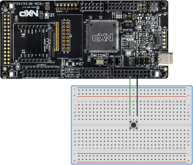
Use a jumper wire to connect pin P3_9 to a rail of a button pin. Use another jumper wire to connect another rail of a button pin to a Ground pin.
Note on the wiring setup
If you're unfamiliar with pull-up resistors you may wonder how, in this setup, a voltage can be sensed at the input pin in the first place. After all, there's no voltage source at the Ground pin leading to the input pin which could be measured. This is because the circuitry within the chip (the FRDM MCX A346 chip) is especially relevant for understanding how pull-up resistors work.
If a pull-up resistor is enabled, the input pin is connected to a power source (VDD) through a single resistor (technically, it is a PMOS transistor acting as a resistor, but for the purpose of this explanation, I will treat it as one). So the input pin senses a constant 3.3V, resulting in a digital "1" reading at the pin if the button is not pressed.
The button is connected to ground without an additional resistor. The input pin is connected to a node between the power source and a resistor on one side of the node and the button and a free path to ground on the other side.
Once the button is pressed there's a path to ground and current can flow. Ohm's law dictates that if there's a current, there's also a voltage drop over the resistor. Since there's only one resistor in the circuit, all the voltage is dropped across that resistor, leaving 0V after the resistor to be measured by the input pin. This results in a digital "0" reading at the pin if the button is pressed.
Note the inverse logic: the input pin reads "1" if the button is not pressed. The input pin reads "0" if the button is pressed.
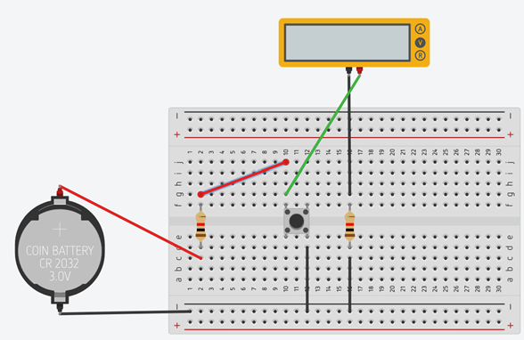
You can simulate a pull-up resistor using Tinkercad or a breadboard setup with a multimeter:
Writing the code to poll the button press and implement a debounce
#include <stdio.h>
#include "board.h"
#include "peripherals.h"
#include "pin_mux.h"
#include "clock_config.h"
#include "fsl_debug_console.h"

int main(void) {

    BOARD_InitBootPins();
    BOARD_InitBootClocks();
    BOARD_InitBootPeripherals();
    //Initiate button pin by calling BOARD_InitBUTTONsPins() in pin_mux.c
    BOARD_InitBUTTONsPins();
#ifndef BOARD_INIT_DEBUG_CONSOLE_PERIPHERAL
    BOARD_InitDebugConsole();
#endif

    PRINTF("Press the button on your breadboard!\r\n");

    while(1) {

    	if (GPIO_PinRead(GPIO3, 9U) == 0U)
    	{
    	    PRINTF("Button Pressed!\r\n");

    	    while(GPIO_PinRead(GPIO3, 9U) == 0U);
    	    //Debounce
    	    SDK_DelayAtLeastUs(20000, CLOCK_GetFreq(kCLOCK_CoreSysClk));
    	}
    }
    return 0 ;
}
Code explanation
while(GPIO_PinRead(GPIO3, 9U) == 0U);
This notation may be confusing, like it's missing something. That's because it is semantically the same as:
while(GPIO_PinRead(GPIO3, 9U) == 0U)
{
//Do nothing as long as while condition remains true (button is pressed)
};
The curly braces can be omitted.
As long as the button is pressed (digital "0" as we learned in the section "Note on
the wiring setup" above) the program will remain in the inner while loop. So the
PRINTF() call ("Button Pressed!") is only called once. Once the button is released,
the voltage at the input pin can return to digital "1" and the condition for the
inner while loop is no longer satisfied and the program can continue. Without this
inner while loop, the terminal would be flooded with "Button pressed!" lines as long
as the button is pressed, since the processor tries to execute the while loop in
main() as fast as possible. Even if the button is pressed only for a brief moment,
PRINTF("Button Pressed!\r\n"); would be executed as long as the button is
pressed.
SDK_DelayAtLeastUs(20000, CLOCK_GetFreq(kCLOCK_CoreSysClk));
But because the button mechanically "bounces" when released, we need to delay the
code execution for a brief period of time. During this bouncing, voltage swings at the
input pin between digital "1" and digital "0" for a couple of milliseconds. So every
time the measurement at the input pin would go from digital "0" to digital "1",
PRINTF("Button Pressed!\r\n"); would be called. Our inner while loop won't help us
anymore, because that while loop is exited as soon as the input pin reads the first
"1" again. We know this debouncing only happens for a couple of milliseconds. That's
why delaying the execution of code for 20 milliseconds is typically enough to
effectively "debounce".
BOARD_InitBUTTONsPins();
The BOARD_InitBUTTONsPins() is not called by default by the program. Unlike the
previous demo, we haven't created a new functional group which the Pins Tool
automatically adds to the BOARD_InitBootPins() function in pin_mux.c. Therefore we
have to write a function call to BOARD_InitBUTTONsPins() ourselves.
Brief explanation of pin P3_9 configuration
PORT3->PCR[9] = ((PORT3->PCR[9] &

                      (~(PORT_PCR_PS_MASK | PORT_PCR_PE_MASK | PORT_PCR_IBE_MASK)))

                     | PORT_PCR_PS(PCR_PS_ps1)

                     | PORT_PCR_PE(PCR_PE_pe1)

                     | PORT_PCR_IBE(PCR_IBE_ibe1));
PORT3->PCR[9] &
Read or grab the current pin configuration of pin P3_9.
~(PORT_PCR_PS_MASK | PORT_PCR_PE_MASK | PORT_PCR_IBE_MASK)
Create a bitmask to clear (set all to zero) the following fields:
PS = pull select
PE = pull enable
IBE = input buffer enable
PORT_PCR_PS(PCR_PS_ps1)
Set pull select to 1 (pull-up; ps0 would set pull-down).
PORT_PCR_PE(PCR_PE_pe1)
Set pull enable to enable (pe0 would disable pull).
Combined with pull select this sets the configuration to: enable pull-up.
PORT_PCR_IBE(PCR_IBE_ibe1)
Set input buffer enable to enable (ibe0 would disable the input buffer).
Note that the code uses macros to improve readability. In a future article I will explain macros in more detail.
In pseudo code:
Pin3_9Configuration = (grab old configuration values)
(clear only the values for PS, PE, IBE)
(set pull-up)
(set enable pull)
(set enable input buffer)
Conclusion