Input Interrupt Demo with NXP FRDM MCX A346
Introduction
This project demonstrates how to use the gpio_input_interrupt SDK example provided by NXP in the MCUXpresso IDE to tailor it to fit your project. In this case we will use the input interrupt to respond to a breadboard button click in addition to the click on the onboard button on the NXP FRDM MCX A346.
In the previous article I have already highlighted the importance of using interrupts over polling in the main function which I will repeat here. Polling consumes CPU cycles continuously, which reduces the time available for other tasks and increases system latency (the time between an event and the system's response to that event), which can become a problem in larger projects. Interrupt-driven GPIO handling avoids this by reacting only when an event occurs. In a later project I will use GPIO Input Interrupt, which is the correct way for handling GPIO Input. GPIO Input Interrupt, for example, offers the possibility to prioritize certain tasks over tasks that are currently running. That's important to consider, since this enables you prioritize an interrupt over other tasks. The ARM Cortex M33 core (the CPU core inside the microcontroller) includes the Nested Vectored Interrupt Controller (NVIC), which supports configurable interrupt priorities and preemption. This allows critical events, such as an emergency stop button press, to interrupt lower priority tasks immediately.
A significant part of this project builds on SDK examples provided by NXP. This is standard practice in embedded development, especially on platforms like the FRDM MCX A346 where community documentation is limited compared to ecosystems such as Arduino or Raspberry Pi.
Professional embedded engineers routinely rely on vendor SDK examples, reference drivers, and documentation to understand how peripherals should be initialized and how specific functions are intended to be used. In many cases, the SDK examples are the most authoritative source for correct implementation.
The project therefore incorporates NXP's example code in accordance with the SDK's licensing terms (article 2.2.(b) of the NXP Software License Agreement), which explicitly allow modification and integration into user applications, as long as the code is used solely in combination with an NXP Product, in this case the FRDM MCX A346.
In this project I will also delve into header files and macros.
Prerequisites
- MCUXpresso IDE installed
- NXP FRDM MCX A346 board
- Breadboard, breadboard button, male jumper wires, LEDs
- Documentation, especially the MCUXpresso Config Tools User's Guide (IDE) (download link) and API documentation
- Familiarity with the Pins Tool (see previous demo)
Configuring the input pin
In the Quickstart Panel (if not visible: Window > Show View > Quickstart Panel) click "Import SDK Example(s)...". We'll select the FRDM MCX A346 board. In the Example view under: driver_examples > gpio, we'll select gpio_input_interrupt and click Finish.
You could pause here and build, debug and resume debug session, to see how the SDK example works before we start adding our own code and setup.
We'll configure the input pin the same way as the previous demo, based on section 3.2 Example workflow of the MCUXpresso Config Tools User's Guide (IDE).
In the Pins Tool, with the current project selected and BOARD_InitBUTTONsPins selected as Functional Group:
1. Select the GPIO3:GPIO,9 signal in the Pins View.
2. Select the Input direction for the GPIO3:GPIO,9 signal in the Routing Details View.
3. Create an Identifier for the GPIO3:GPIO,9 signal in the Pins View. Create the value MY_INPUT_P3_9 as identifier.
4. Set the identifier (MY_INPUT_P3_9) for the pin in the Routing Details View.
5. Set the pull select to pull-up in the Routing Details View.
6. Enable the pull (in the cell to the right) in the Routing Details View.
7. Click Update Code. Click OK in the dialog box.
The SDK example includes a call to BOARD_InitHardware() by default. Using Open Declaration (right click) on this function shows that it calls BOARD_InitBUTTONsPins() in pin_mux.c. This function was automatically generated by the Pins Tool and contains the pin configuration code required to initialize pin P3_9 for the breadboard button input.
Header files
Header files are the files in your project folders which end with .h.
Using header files to declare function prototypes is essential because it tells the compiler the function's signature (its return type and parameter types) before the function is used. Without this information, the compiler must guess how to call the function, which can lead to incorrect argument passing and unpredictable results.
For example, consider this incorrect code:
int main()
{
    printMultipleOfThreeIntegers(2, 3);    //missing one argument
}
The function is actually defined with three parameters instead of two:
printMultipleOfThreeIntegers(int a, int b, int c)
{
    int result3 = a * b * c;
    char multiplebuffer3[100];
    sprintf(multiplebuffer3, "Result is: %i", result3);
    printf("%s\n", multiplebuffer3);
}
Because the compiler has not seen a prototype, it assumes an old style declaration:
int printMultipleOfThreeIntegers(int a, int b, int c);This causes the arguments to be passed incorrectly according to the processors calling convention, and, depending on the compiler, the program will still run but the function receives garbage values (e.g., "Result is: 1614907702") or the compiler throws errors like:
error: implicit declaration of function 'printMultipleOfThreeIntegers'
If we instead declare the function in a header file:
void printMultipleOfThreeIntegers(int a, int b, int c);...the compiler immediately reports the mistake:
error: too few arguments to function 'printMultipleOfThreeIntegers'
This prevents subtle bugs and ensures the compiler generates the correct calling sequence.
Macros and header files
Header files can also define macros, which are names (often written in capital letters) that the preprocessor replaces with values, expressions, or even blocks of code before compilation. Macros can make code more readable, reduce repetition, and centralize configuration, although they should be used carefully.
An example:
The header file (my_header_file.h) would simply read:
#define GOOD "supercalifragilisticexpialidocious"The code could look like:
#include " my_header_file.h "
...
int main()
{
    PRINTF("That long word for good is %s.", GOOD);
}
This would output "That long word for good is supercalifragilisticexpialidocious." to the terminal.
The first macro we can discover in the SDK example is BOARD_SW_IRQ_HANDLER. If we right click > Open Declaration, we see this is defined as BOARD_SW2_IRQ_HANDLER. Again, if we right click > Open Declaration, we see this is defined as GPIO1_IRQHandler, which is the actual name of the function.
Again, if we right click > Open Declaration, we see:
WEAK void GPIO1_IRQHandler(void)
{
    GPIO1_DriverIRQHandler();
}
This is a weak symbol.
Weak vs. strong symbols
A strong symbol is a normal function in C:
void MyFunction()
{
    // Do stuff
}
A weak symbol is a placeholder. If the programmer does not provide an implementation the program will just use the weak symbol. But the programmer is free to override the weak symbol, which is exactly what the authors of the SDK example did in the BOARD_SW_IRQ_HANDLER() function.
This gives us an important hint for our own setup with a breadboard button which is connected to a GPIO3 pin.
Why these placeholders exist in the first place
When a microcontroller reacts to a button press, it must jump from whatever it was doing to a specific piece of code immediately. To make this possible, ARM Cortex M chips include a hardware block called the Nested Vectored Interrupt Controller (NVIC). Its job is simple:
When hardware needs attention, the NVIC tells the CPU exactly which function to run.
To do that, the NVIC relies on a predefined lookup table called the vector table. This table lives in the startup code (for example, startup_MCXA346.c) and contains a list of function pointers, one for each interrupt source.
These function pointers are the "landing spots" for hardware events.
The SDK must provide something in the vector table for every possible interrupt, even if the programmer doesn't use them. That's why the SDK includes weak placeholder functions like:
WEAK void GPIO1_IRQHandler(void)
{
    GPIO1_DriverIRQHandler();
}
These placeholders ensure:
- the vector table is always complete
- the program links successfully
- the user can override only the handlers they need
When you write your own handler with the same name, your version automatically replaces the weak one.
Here's the simplified story of what happens when a button is pressed:
1. A hardware event occurs The GPIO pin detects a change (button press) and signals the NVIC.
2. The NVIC checks if the interrupt is allowed to run It looks at enable bits and priority settings.
3. The CPU pauses what it was doing It automatically saves registers so it can resume later.
4. The CPU looks up the correct handler in the vector table The vector table contains the address of GPIO1_IRQHandler().
5. The CPU jumps to that handler function This is the "landing spot" for the interrupt.
6. Your interrupt code runs Whatever you wrote inside the handler executes.
7. The handler returns You finish handling the event.
8. The CPU restores the saved registers It puts everything back the way it was.
9. Normal program execution continues As if nothing happened.
The vector table is the bridge between hardware events and your C functions.
It tells the CPU: "When this interrupt happens, jump to this function."
Without this bridge, the CPU would have no idea where to go when a button is pressed.
The CPU needs a predefined place in the program where a hardware event can "land". The vector table provides this mapping: each interrupt source is linked to a specific function. When the event occurs, the CPU uses the vector table to jump directly to the correct handler, where the programmer's code runs. This mechanism forms the essential bridge between hardware signals and software behavior.
This also means we can use another weak placeholder function and override it for handling the interrupt request for GPIO3: void GPIO3_IRQHandler(void). After all, our breadboard button is connected to a GPIO3 pin, so the breadboard button press will be a hardware event which will be mapped to that function.
Code for GPIO interrupt after breadboard button press
#include "fsl_debug_console.h"
#if defined(FSL_FEATURE_SOC_PORT_COUNT) && (FSL_FEATURE_SOC_PORT_COUNT)
#include "fsl_port.h"
#endif
#include "fsl_gpio.h"
#include "fsl_common.h"
#include "app.h"
#include "pin_mux.h"
#include "board.h"

volatile bool g_ButtonPress = false;
//Insert the Boolean for our breadboard button
volatile bool my_BreadboardButtonPress = false;

void BOARD_SW_IRQ_HANDLER(void)
{
#if (defined(FSL_FEATURE_PORT_HAS_NO_INTERRUPT) && FSL_FEATURE_PORT_HAS_NO_INTERRUPT) || \
    (!defined(FSL_FEATURE_SOC_PORT_COUNT))
    GPIO_GpioClearInterruptFlags(BOARD_SW_GPIO, 1U << BOARD_SW_GPIO_PIN);
#else
    GPIO_PortClearInterruptFlags(BOARD_SW_GPIO, 1U << BOARD_SW_GPIO_PIN);
#endif
    g_ButtonPress = true;
    SDK_ISR_EXIT_BARRIER;
}

//Insert the equivalent handler for GPIO3
void GPIO3_IRQHandler(void)
{
    GPIO_GpioClearInterruptFlags(GPIO3, 1U << 9U);
    my_BreadboardButtonPress = true;
}

int main(void)
{
    gpio_pin_config_t sw_config = {
        kGPIO_DigitalInput,
        0,
    };

    gpio_pin_config_t led_config = {
        kGPIO_DigitalOutput,
        0,
    };

    BOARD_InitHardware();

    PRINTF("\r\n GPIO Driver example\r\n");
    //Adjust the terminal message to our setup
    PRINTF("\r\n Press %s or the breadboard button to turn on/off a LED \r\n", BOARD_SW_NAME);

#if (defined(FSL_FEATURE_PORT_HAS_NO_INTERRUPT) && FSL_FEATURE_PORT_HAS_NO_INTERRUPT) || \
    (!defined(FSL_FEATURE_SOC_PORT_COUNT))
    GPIO_SetPinInterruptConfig(BOARD_SW_GPIO, BOARD_SW_GPIO_PIN, kGPIO_InterruptFallingEdge);
    //Insert our equivalent code
    GPIO_SetPinInterruptConfig(GPIO3, 9U, kGPIO_InterruptFallingEdge);
#else
    PORT_SetPinInterruptConfig(BOARD_SW_PORT, BOARD_SW_GPIO_PIN, kPORT_InterruptFallingEdge);
#endif
    EnableIRQ(BOARD_SW_IRQ);
    //Insert our equivalent code
    EnableIRQ(GPIO3_IRQn);
    //GPIO3_9 is already initiated in pin_mux.c
    GPIO_PinInit(BOARD_SW_GPIO, BOARD_SW_GPIO_PIN, &sw_config);

    GPIO_PinInit(BOARD_LED_GPIO, BOARD_LED_GPIO_PIN, &led_config);

    while (1)
    {
        if (g_ButtonPress)
        {
            PRINTF(" %s is pressed \r\n", BOARD_SW_NAME);
            GPIO_PortToggle(BOARD_LED_GPIO, 1U << BOARD_LED_GPIO_PIN);
            g_ButtonPress = false;
        }

        //Insert our equivalent code
        if (my_BreadboardButtonPress)
        {
            PRINTF("Breadboard button is pressed \r\n");
            GPIO_PortToggle(BOARD_LED_GPIO, 1U << BOARD_LED_GPIO_PIN);
            while(GPIO_PinRead(GPIO3, 9U) == 0U);
            SDK_DelayAtLeastUs(20000, CLOCK_GetFreq(kCLOCK_CoreSysClk));
            my_BreadboardButtonPress = false;
        }
    }
}
Wiring
Use a jumper wire to connect pin P3_9 to a rail of a button pin. Use another jumper wire to connect another rail of a button pin to a Ground pin.
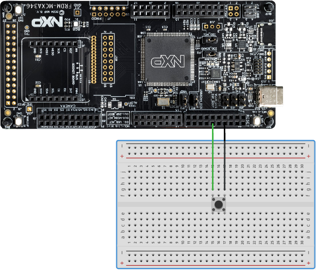
You can now build, debug and resume debug session and you've successfully implemented a GPIO interrupt for a breadboard button.
There is much more to learn about interrupts. Why should you use the volatile keyword? The FRDM MCX A346 has a single core processor. What difference would it make of it had a multicore processor? I will cover questions like these in future articles.
LED Chaser pin configuration
If you came here for the configuration and code of the LED chaser, then here it is. In addition to configuration steps under "Configuring the input pin" section:
In the Pins Tool, with the current project selected and BOARD_InitLEDsPins selected as Functional Group:
1. Select the GPIO3:GPIO,17, GPIO3:GPIO,16, GPIO3:GPIO,15, GPIO3:GPIO,13, GPIO3:GPIO,12 signals in the Pins View.
2. Select the Output direction for the GPIO3:GPIO,17, GPIO3:GPIO,16, GPIO3:GPIO,15, GPIO3:GPIO,13, GPIO3:GPIO,12 signals in the Routing Details View.
3. Create Identifiers for the GPIO3:GPIO,17, GPIO3:GPIO,16, GPIO3:GPIO,15, GPIO3:GPIO,13, GPIO3:GPIO,12 signals in the Pins View. Create the values MY_OUTPUT_P3_17, MY_OUTPUT_P3_16, MY_OUTPUT_P3_15, MY_OUTPUT_P3_13, MY_OUTPUT_P3_12, as identifiers.
4. Set the identifiers for the pins in the Routing Details View.
5. Click Update Code. Click OK in the dialog box.
Full code LED Chaser
#include "fsl_debug_console.h"
#if defined(FSL_FEATURE_SOC_PORT_COUNT) && (FSL_FEATURE_SOC_PORT_COUNT)
#include "fsl_port.h"
#endif
#include "fsl_gpio.h"
#include "fsl_common.h"
#include "app.h"
#include "pin_mux.h"
#include "board.h"

volatile bool g_ButtonPress = false;
//Insert the Boolean for our breadboard button
volatile bool my_BreadboardButtonPress = false;

void BOARD_SW_IRQ_HANDLER(void)
{
#if (defined(FSL_FEATURE_PORT_HAS_NO_INTERRUPT) && FSL_FEATURE_PORT_HAS_NO_INTERRUPT) || \
    (!defined(FSL_FEATURE_SOC_PORT_COUNT))
    GPIO_GpioClearInterruptFlags(BOARD_SW_GPIO, 1U << BOARD_SW_GPIO_PIN);
#else
    GPIO_PortClearInterruptFlags(BOARD_SW_GPIO, 1U << BOARD_SW_GPIO_PIN);
#endif
    g_ButtonPress = true;
    SDK_ISR_EXIT_BARRIER;
}

//Insert the equivalent handler for GPIO3
void GPIO3_IRQHandler(void)
{
    GPIO_GpioClearInterruptFlags(GPIO3, 1U << 9U);
    my_BreadboardButtonPress = true;
}

void startLEDChaser(void)
{
	int loopCount = 0;
	uint32_t led_ms = 500000;

	while(loopCount < 20)
	{
		GPIO_PinWrite(GPIO3, 12U, 1);
		SDK_DelayAtLeastUs(led_ms, CLOCK_GetFreq(kCLOCK_CoreSysClk));
		GPIO_PinWrite(GPIO3, 12U, 0);
		GPIO_PinWrite(GPIO3, 13U, 1);
		SDK_DelayAtLeastUs(led_ms, CLOCK_GetFreq(kCLOCK_CoreSysClk));
		GPIO_PinWrite(GPIO3, 13U, 0);
		GPIO_PinWrite(GPIO3, 15U, 1);
		SDK_DelayAtLeastUs(led_ms, CLOCK_GetFreq(kCLOCK_CoreSysClk));
		GPIO_PinWrite(GPIO3, 15U, 0);
		GPIO_PinWrite(GPIO3, 16U, 1);
		SDK_DelayAtLeastUs(led_ms, CLOCK_GetFreq(kCLOCK_CoreSysClk));
		GPIO_PinWrite(GPIO3, 16U, 0);
		GPIO_PinWrite(GPIO3, 17U, 1);
		SDK_DelayAtLeastUs(led_ms, CLOCK_GetFreq(kCLOCK_CoreSysClk));
		GPIO_PinWrite(GPIO3, 17U, 0);
		loopCount++;
		led_ms = led_ms * 0.8;
	}

	int finishLoopCount = 0;

	while(finishLoopCount < 4)
	{
		GPIO_PinWrite(GPIO3, 12U, 1);
		GPIO_PinWrite(GPIO3, 13U, 1);
		GPIO_PinWrite(GPIO3, 15U, 1);
		GPIO_PinWrite(GPIO3, 16U, 1);
		GPIO_PinWrite(GPIO3, 17U, 1);
		SDK_DelayAtLeastUs(500000, CLOCK_GetFreq(kCLOCK_CoreSysClk));
		GPIO_PinWrite(GPIO3, 12U, 0);
		GPIO_PinWrite(GPIO3, 13U, 0);
		GPIO_PinWrite(GPIO3, 15U, 0);
		GPIO_PinWrite(GPIO3, 16U, 0);
		GPIO_PinWrite(GPIO3, 17U, 0);
		SDK_DelayAtLeastUs(500000, CLOCK_GetFreq(kCLOCK_CoreSysClk));
		finishLoopCount++;
	}
}

int main(void)
{
    gpio_pin_config_t sw_config = {
        kGPIO_DigitalInput,
        0,
    };

    gpio_pin_config_t led_config = {
        kGPIO_DigitalOutput,
        0,
    };

    BOARD_InitHardware();

    PRINTF("\r\n GPIO Driver example\r\n");
    //Adjust the terminal message to our setup
    PRINTF("\r\n Press %s or the breadboard button to turn on/off a LED \r\n", BOARD_SW_NAME);

#if (defined(FSL_FEATURE_PORT_HAS_NO_INTERRUPT) && FSL_FEATURE_PORT_HAS_NO_INTERRUPT) || \
    (!defined(FSL_FEATURE_SOC_PORT_COUNT))
    GPIO_SetPinInterruptConfig(BOARD_SW_GPIO, BOARD_SW_GPIO_PIN, kGPIO_InterruptFallingEdge);
    //Insert our equivalent code
    GPIO_SetPinInterruptConfig(GPIO3, 9U, kGPIO_InterruptFallingEdge);
#else
    PORT_SetPinInterruptConfig(BOARD_SW_PORT, BOARD_SW_GPIO_PIN, kPORT_InterruptFallingEdge);
#endif
    EnableIRQ(BOARD_SW_IRQ);
    //Insert our equivalent code
    EnableIRQ(GPIO3_IRQn);
    //GPIO3_9 is already initiated in pin_mux.c
    GPIO_PinInit(BOARD_SW_GPIO, BOARD_SW_GPIO_PIN, &sw_config);

    GPIO_PinInit(BOARD_LED_GPIO, BOARD_LED_GPIO_PIN, &led_config);

    while (1)
    {
        if (g_ButtonPress)
        {
            PRINTF(" %s is pressed \r\n", BOARD_SW_NAME);
            GPIO_PortToggle(BOARD_LED_GPIO, 1U << BOARD_LED_GPIO_PIN);
            g_ButtonPress = false;
        }

        //Insert our equivalent code
        if (my_BreadboardButtonPress)
        {
            PRINTF("Breadboard button is pressed \r\n");
            GPIO_PortToggle(BOARD_LED_GPIO, 1U << BOARD_LED_GPIO_PIN);
        startLEDChaser();
            while(GPIO_PinRead(GPIO3, 9U) == 0U);
            SDK_DelayAtLeastUs(20000, CLOCK_GetFreq(kCLOCK_CoreSysClk));
            my_BreadboardButtonPress = false;
        }
    }
}
In app.h (in your Project Folder > board) declare the startLEDChaser() function. app.h should look like this:
#ifndef _APP_H_
#define _APP_H_

#include "board.h"

/*******************************************************************************
 * Definitions
 ******************************************************************************/
/*${macro:start}*/
#define BOARD_LED_GPIO       BOARD_LED_RED_GPIO
#define BOARD_LED_GPIO_PIN   BOARD_LED_RED_GPIO_PIN
#define BOARD_SW_GPIO        BOARD_SW2_GPIO
#define BOARD_SW_GPIO_PIN    BOARD_SW2_GPIO_PIN
#define BOARD_SW_NAME        BOARD_SW2_NAME
#define BOARD_SW_IRQ         BOARD_SW2_IRQ
#define BOARD_SW_IRQ_HANDLER BOARD_SW2_IRQ_HANDLER
/*${macro:end}*/

/*******************************************************************************
 * Prototypes
 ******************************************************************************/
/*${prototype:start}*/
void BOARD_InitHardware(void);
void startLEDChaser(void);    //declare startLEDChaser()
/*${prototype:end}*/

#endif /* _APP_H_ */
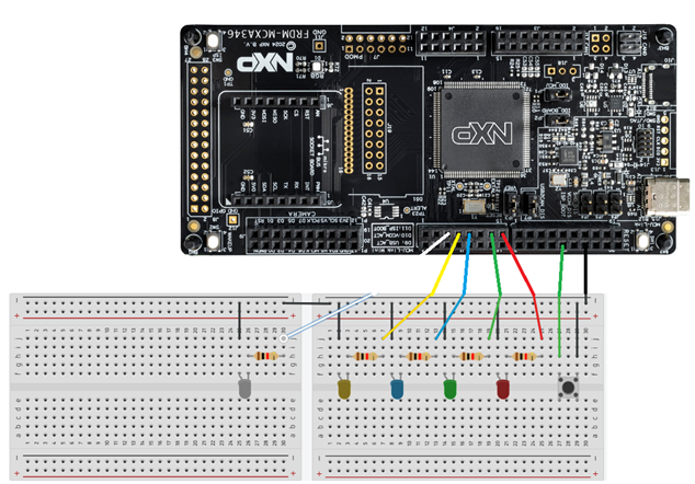
Breadboard and wiring LED Chaser
Conclusion
Further reading