Writing and Reading a GPIO Pin Demo with NXP FRDM MCX A346
Introduction
This project demonstrates the GPIO_PinWrite() and GPIO_PinRead() functions on the NXP FRDM MCX A346 development board. But more importantly, it demonstrates the Pins Tool which is part of the MCUXpresso IDE and how it helps you to configure the pins correctly to successfully write to and read from the pins. It also highlights the importance of reading the documentation. It will save you hours of working through bus faults or only reading zeros from the input pins, even if there's sufficient voltage present at the input pin.
Follow the instructions below in case of bus errors or if you're only reading zeros at input pins
You may have landed on this page if you're getting a bug report saying: "Active faults @ startup_MCXA346.c [line 796]" or if you're only reading zeros at an input pin even though you've checked for sufficient voltage present, this demo may offer a bugfix.
Prerequisites
- MCUXpresso IDE installed
- NXP FRDM MCX A346 board
- Jumper wire
- Documentation, especially the MCUXpresso Config Tools User's Guide (IDE) (download link) and API documentation
Before you start configuring and coding
Create a new C Project.
Before you start any coding, I want you to open pin_mux.c and pin_mux.h (in your project folder > board). If you take a look at pin_mux.c you'll notice by scrolling through the file or by looking at the outline (if not visible: Window > Show View > Other... > under General > click Outline), a list of functions (BOARD_InitBootPins(void), BOARD_InitDEBUG_UARTPins(void), etc.). Note that there's no function called BOARD_InitGPIOPins(void). In the pin_mux.h file you won't find any function called BOARD_InitGPIOPins(void) either. Neither will you find any macros named BOARD_INITGPIOPINS_MY_OUTPUT_GPIO. Remember that for later.
Using the Pins Tool to configure the output and input pins (GPIO)
On the menu bar, click Config Tools > Pins
Make sure you have your current project selected in the drop down menu in the Pins Tool.

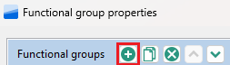
With your project selected, click the Functional Group Properties button.

In the Functional Group Properties dialog box click the Add a new functional group button.
Change the name to BOARD_InitGPIOPins and click OK.
Now you should have BOARD_InitGPIOPins selected as the functional group you are configuring using the Pins Tool.

Following the MCUXpresso Config Tools User's Guide (IDE)
From here we can follow along with the documentation in the MCUXpresso Config Tools User's Guide (IDE) at section 3.2 Example workflow, tailored to our setup. So part of the text below follows the documentation's text almost exactly.
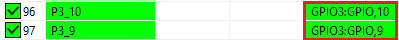
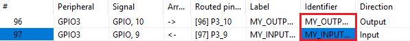
In this example, two pins (GPIO3:GPIO,10 and GPIO3:GPIO,9) are configured.
1. In the Pins view, select the GPIO3:GPIO,10 and GPIO3:GPIO,9 signals. For it, you can click into the cells to make them 'green'.
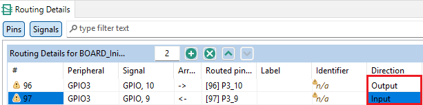
2. In the Routing Details view, select the Output direction for the GPIO3:GPIO,10 signal. Select the Input direction for the GPIO3:GPIO,9 signal.
3. You'll notice warning signs. To address these warnings create Identifiers in the Pins View for the GPIO3:GPIO,10 and GPIO3:GPIO,9 signals. We'll create the values "MY_OUTPUT_P3_10" and "MY_INPUT_P3_9" as identifiers.
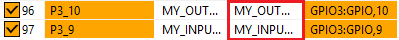
4. Next we actually set the identifiers for the pins in the Routing Details View.
5. To finish, click Update Code. Click OK in the dialog box.
If we look at the pin_mux.c code, Inside the BOARD_InitBootPins() function, an initialization call has automatically been generated.
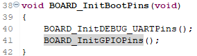
If you scroll down to the bottom of your pin_mux.c file you'll notice the BOARD_InitGPIOPins() function. Inside it you'll see the necessary code which has been generated automatically for the correct pin configuration. In the pin_mux.h file, code has automatically been generated as well.
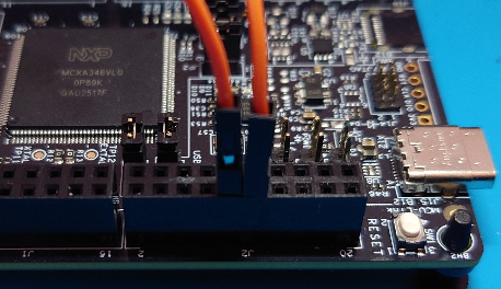
Wiring pin P3_10 to pin P3_9
For this simple project we only use a single wire to connect P3_10 to P3_9. Use the Quick Start Guide leaflet, which came inside the box with the FRDM MCX A346 board itself, to see where the pins are located.
Writing the code using the GPIO_PinWrite() and GPIO_PinRead() functions
#include
#include "board.h"
#include "peripherals.h"
#include "pin_mux.h"
#include "clock_config.h"
#include "fsl_debug_console.h"

int main(void) {

    BOARD_InitBootPins();
    BOARD_InitBootClocks();
    BOARD_InitBootPeripherals();
#ifndef BOARD_INIT_DEBUG_CONSOLE_PERIPHERAL
    BOARD_InitDebugConsole();
#endif

    PRINTF("Hello World\r\n");

    volatile static int i = 0 ;
    uint32_t digitalValueReadFromPinP3_9 = 0;

    while(1) {
        i++ ;

        PRINTF("Loop no.: %d\r\n", i);

		SDK_DelayAtLeastUs(500000, CLOCK_GetFreq(kCLOCK_CoreSysClk));
		GPIO_PinWrite(GPIO3, 10U, 1);

		SDK_DelayAtLeastUs(500000, CLOCK_GetFreq(kCLOCK_CoreSysClk));
		digitalValueReadFromPinP3_9 = GPIO_PinRead(GPIO3, 9U);
		PRINTF("Value = %d\r\n", digitalValueReadFromPinP3_9);

		SDK_DelayAtLeastUs(500000, CLOCK_GetFreq(kCLOCK_CoreSysClk));
		GPIO_PinWrite(GPIO3, 10U, 0);

		SDK_DelayAtLeastUs(500000, CLOCK_GetFreq(kCLOCK_CoreSysClk));
		digitalValueReadFromPinP3_9 = GPIO_PinRead(GPIO3, 9U);
		PRINTF("Value = %d\r\n", digitalValueReadFromPinP3_9);

		SDK_DelayAtLeastUs(500000, CLOCK_GetFreq(kCLOCK_CoreSysClk));
		GPIO_PinRead(GPIO3, 9U);
    }
    return 0 ;
}
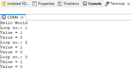
If you Build, Debug and Resume Debug session the terminal output should now look like this:
Code explanation
GPIO_PinWrite()
Sets the output level of a GPIO pin to the logic 1 or 0. This function takes 3 parameters:
base: GPIO peripheral block (in our case "GPIO3")pin: GPIO pin number (in our case "10U")output: output logic level. 0 for low-logic level, 1 for high-logic level
GPIO_PinRead()
Reads the input value of a GPIO pin. This function takes 2 parameters:
base: GPIO peripheral block (in our case "GPIO3")pin: GPIO pin number (in our case "9U")
BOARD_InitBootPins()
This function is generated by the Pins Tool and defined in pin_mux.c. It serves as the entry point for pin initialization and calls BOARD_InitGPIOPins(). Thus, invoking BOARD_InitBootPins() in main() applies all the pin settings we configured using the Pins Tool.
Understanding %d syntax
The PRINTF() function in the MCUXpresso SDK is essentially a wrapper around the
standard C library's printf(). It follows the same rules for format specifiers. is the
format specifier for printing an integer in decimal form. %d is the format specifier
for printing an integer in decimal form. It tells PRINTF(): "Expect an integer argument
and print it as a signed decimal number." The comma , separates function parameters.
The comma is followed by the variable which is the actual data that gets substituted
into the format string.
In our case we used %d, because we were dealing with an integer in decimal form, but
there are more specifiers we can use like %f for decimal floating points, %f%s for
strings of characters, etc.
Understanding \r and \n syntax
\r: moves the cursor to the start of the current line
\n: moves the cursor down a line
So for example:
PRINTF("Hello World! It is great to see you!\r\n");
PRINTF("Printing more text\r\n");
With \r\n the terminal output looks like this:
Hello World! It is great to see you!
Printing more text
With \r only the terminal output looks like this:
Printing more text great to see you!With \n only the terminal output looks like this:
Hello World! It is great to see you!
                                    Printing more text
Without either the terminal output looks like this:
Hello World! It is great to see you!Printing more textConclusion
You have learned to effectively use the MCUXpresso's Pins Tool to correctly configure GPIO pins, using the documentation provided by NXP. You've learned how to write digital logic to pins and how to read digital input logic from pins.
In future articles I may also write about header files and macros. So stay tuned to learn more about Embedded C on professional development boards.