Traffic Light Blinky Demo with NXP FRDM MCX A346
Introduction
This project demonstrates how to blink multiple LEDs on a breadboard using the NXP FRDM MCX A346 development board, simulating a simple traffic light. It goes beyond the standard MCUXpresso SDK examples and shows how hobbyists can take their first steps into professional embedded programming. The goal is to highlight both accessibility for newcomers and transferable skills in embedded C, hardware setup, and debugging.
About this series
I am a hobby programmer with a strong interest in robotics. My background includes Arduino Uno projects, which are widely used for prototyping. In professional settings, however, engineers often transition to boards from NXP or STMicroelectronics. I wanted to explore how different the experience is when moving from Arduino to professional boards and IDEs, especially since tutorials for hobbyists are limited.
My first impression: it's a noticeable shift, but not overwhelming. NXP's documentation and tools make the process approachable. Setting up the IDE, installing the SDK, and importing example projects has been straightforward. This series aims to show that embedded programming with professional tools is within reach for hobbyists - it just requires a different learning approach.
Prerequisites
- MCUXpresso IDE installed
- NXP FRDM MCX A346 board
- SDK example
gpio_led_output(found under driver_examples > gpio) - Breadboard, LEDs, resistors, and jumper wires
To import SDK examples: open the Quickstart Panel in MCUXpresso IDE and select Import SDK example(s).... If the panel is hidden, go to Window > Show View > Quickstart Panel.
Starting the Traffic Light Demo
- Create a new C project in MCUXpresso IDE.
- Copy
app.handhardware_init.cfrom thegpio_led_outputexample (found under board) into the board folder of your new project. - Ensure the Project Explorer is visible: Window > Show View > Project Explorer.
Code
#include "board.h"
#include "fsl_debug_console.h"
#include "fsl_gpio.h"
#include "app.h"
#include "fsl_common.h"
int main(void)
{
gpio_pin_config_t led_config = {
kGPIO_DigitalOutput,
0,
};
BOARD_InitHardware();
GPIO_PinInit(GPIO3, 10, &led_config); // Red LED
GPIO_PinInit(GPIO3, 9, &led_config); // Yellow LED
GPIO_PinInit(GPIO3, 8, &led_config); // Green LED
while (1)
{
GPIO_PortToggle(GPIO3, 1u << 10); // Red on
SDK_DelayAtLeastUs(2000000, CLOCK_GetFreq(kCLOCK_CoreSysClk));
GPIO_PortToggle(GPIO3, 1u << 10); // Red off
GPIO_PortToggle(GPIO3, 1u << 8); // Green on
SDK_DelayAtLeastUs(1000000, CLOCK_GetFreq(kCLOCK_CoreSysClk));
GPIO_PortToggle(GPIO3, 1u << 8); // Green off
GPIO_PortToggle(GPIO3, 1u << 9); // Yellow on
SDK_DelayAtLeastUs(500000, CLOCK_GetFreq(kCLOCK_CoreSysClk));
GPIO_PortToggle(GPIO3, 1u << 9); // Yellow off
}
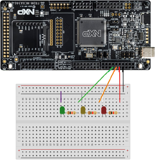
}Breadboard and wiring
Connect the LEDs to GPIO pins 8, 9, and 10 of GPIO3, each with a suitable resistor. Ensure correct polarity (anode to GPIO, cathode to ground). See Figure 1 for wiring layout.
Troubleshooting
- If LEDs behave unexpectedly, check for loose or touching wires.
- Verify LED orientation (anode vs. cathode).
- Confirm resistor values are appropriate.
Code explanation
gpio_pin_config_t
This structure configures a GPIO pin:
pinDirection: input or output (here,kGPIO_DigitalOutput)outputLogic: default logic level (0 = low, 1 = high)
GPIO_PinInit()
Initializes a GPIO pin with three parameters:
base: GPIO peripheral blockpin: GPIO pin numberconfig: pointer to configuration structure
GPIO_PortToggle()
Toggles the state of one or more pins on a GPIO port. The mask parameter uses bit
shifting to select the pin. For example, 1u << 10 creates a mask for pin 10.
Understanding syntax in Embedded C
When I first started embedded programming, I found the syntax confusing - especially
symbols like {}, *, and <<. Over time, I realized that each programming language has
consistent rules for how these symbols work. Here's a breakdown of what they mean in
embedded C, using examples from this project.
{} - Struct initialization
Curly braces are used to initialize a structure. For example:
gpio_pin_config_t led_config = {
    kGPIO_DigitalOutput,
    0,
};
This sets the pinDirection to output and the outputLogic to low (0 volts). The values
inside the braces match the order of fields in the gpio_pin_config_t struct.
* - Pointer indicator
The asterisk denotes a pointer, which holds the memory address of another variable. Example:
const gpio_pin_config_t *configThis means the function expects a pointer to a gpio_pin_config_t structure. When calling:
GPIO_PinInit(GPIO3, 10, &led_config);we pass the address of led_config using &.
& - Address-of operator
The ampersand symbol means "address of". It's how you pass a variable's memory location to a function that expects a pointer.
Example:
&led_configThis gives the function direct access to the struct in memory, rather than a copy.
<< - Bitwise shift operator
The shift operator moves bits left or right. It's used to create bitmasks for selecting pins.
Example:
1u << 10This shifts the binary value 1 left by 10 positions, producing a mask that targets pin 10.
u - Unsigned integer suffix
Adding u after a number makes it an unsigned integer.
Example:
1uThis ensures the value is treated as non-negative, which is important for bitwise operations. Using 1u avoids unexpected behavior when shifting bits.
Referencing the correct GPIO block
When working with microcontrollers, documentation often refers to GPIO blocks as GPIOA, GPIOB, GPIOC, etc. On the NXP FRDM MCX A346, however, the GPIO blocks are numbered: GPIO1, GPIO2, GPIO3, and so on.
How You Can Identify the Right Block
- Use the Pins View in MCUXpresso IDE : Go to Window > Show View > Pins. This shows all available pins and their functions. Each pin entry lists the GPIO block it belongs to.
- Check the Quick Start Guide: The printed guide that comes with the FRDM board maps physical pin names to their GPIO blocks. For example, pin D13/SCK might be listed as belonging to GPIO3.
Conclusion
This demo illustrates how hobbyists can step into professional embedded programming using NXP boards and MCUXpresso IDE. By leveraging documentation, SDK examples, and structured experimentation, it's possible to learn effectively without relying solely on tutorials. Future projects may explore interrupts, timers, or more complex peripherals, continuing the journey toward professional grade embedded development.