LED dimming Demo using PWM with NXP FRDM MCX A346
Introduction
Although this project uses the PWM (Pulse Width Modulator) driver to dim an LED, its real purpose is to serve as a minimal introduction to motor control concepts. I will explain why the PWM SDK example for the NXP FRDM MCX A346 is written with safety critical applications - such as motor control - in mind, even though we are starting with something as simple as LED dimming.
In a future article, I will show why CTimer is often a more appropriate choice for lightweight tasks like LED dimming. LED projects are fun and visually satisfying, but ultimately we want to progress toward more serious robotics work, where (advanced) motor control becomes essential. If our long term goal is to build industrial grade cobots, then brushless DC motor control using PWM is a fundamental requirement. It matters for compliance (human safety), equipment protection, accuracy, repeatability, long duty cycles, and payload capacity.
For that reason, we will begin with an introductory project using PWM rather than CTimer. CTimer is useful, but it leads us down a side path, whereas PWM is the direction we ultimately need to master.
We will still examine the PWM SDK example, because our LED dimming project will be based on it - albeit in a trimmed down form. Along the way, I will explain which features we remove, why they are essential for motor control, and why they can be safely omitted for a simple LED. I will also highlight one feature - fault handling - that could be removed for an LED project, but doing so would prevent the FRDM MCX A346 from lighting the LED at all, due to its safety-by-design architecture.
Prerequisites
- MCUXpresso IDE installed
- NXP FRDM MCX A346 board
- Breadboard, 9 male jumper wires, 4 LEDs, 4 resistors
- Documentation, especially the MCUXpresso Config Tools User's Guide (IDE) (download link) and API documentation
- Familiarity with breadboarding and using the Pins Tool (see previous demo)
Taking a look at the PWM SDK example
In the Quickstart Panel (if not visible: Window > Show View > Quickstart Panel) click "Import SDK Example(s)...". We'll select the FRDM MCX A346 board. In the Example view under: driver_examples > pwm, we'll select pwm and click Finish.
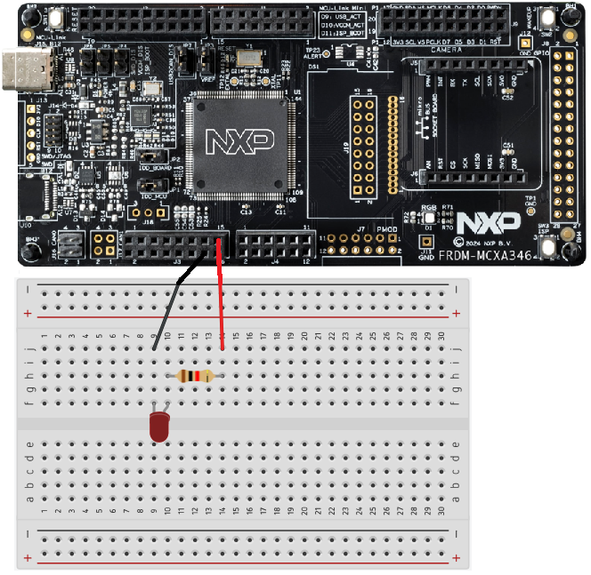
If we take a look at the example_board_readme.md (in your Project Folder > doc) it looks like we need an oscilloscope to test the SDK example. However, to see whether the SDK example actually works, we can also use a breadboard setup with LEDs. We can connect pins P3_0, P3_1, P3_8 and P3_10 to LEDs on a breadboard through appropriate resistors and see the LEDs dim.
In the next part of this section we will take a look at some essential features of the PWM SDK example for motor control.
Dead-time insertion
DC motors are typically driven using H-bridges or half-bridges built from MOSFETs - transistors that act like very fast electronic switches. These switches control both the speed and direction of the motor.
When the bridge switches from one state to another, there's a brief moment where both MOSFETs on one side could accidentally be on at the same time. This creates a direct short circuit, known as shoot-through, which can destroy the MOSFETs long before the motor even notices anything is wrong.
Dead-time insertion prevents this. It adds a tiny delay - about 650 nanoseconds in the SDK example - where neither MOSFET is allowed to conduct. This gives the hardware time to switch cleanly and eliminates the risk of shoot-through. Dead time is a short, deliberate pause where both MOSFETs are commanded OFF, ensuring clean switching and preventing shoot-through.
Even though we don't need this level of protection for a simple LED, it's essential for real motor control, which is why the PWM example includes it by default.
Complementary pair operation
So MOSFETs act as high speed switches in motor control circuits. To drive a DC motor efficiently and control its speed, torque, and direction, the motor is powered through these half-bridges or H-bridges made of two MOSFETs working as a complementary pair. When one MOSFET turns on, the other must turn off in perfect coordination.
This complementary pair operation, combined with PWM, allows precise control of motor current. It also enables dead-time insertion, a short delay that ensures both MOSFETs are off during switching. This prevents shoot through, a destructive short circuit that can occur in motor drivers.
LEDs don't use half bridges, so they don't need complementary operation or dead-time - which is why these features are essential for motor control but unnecessary for simple LED dimming.
Fault handling
Fault handling isn't needed for simple LED dimming, but the PWM module is designed for motor-control safety, so it won't enable its outputs unless fault handling is properly configured. In motor applications, fault handling acts as an emergency shutdown mechanism that protects the MOSFETs and power stage from overcurrent, short circuits, or other dangerous conditions.
Because PWM defaults to "outputs off until faults are configured and cleared", we must keep the fault-handling setup in place - even though the LED itself doesn't need this protection.
Dimming an LED using the SDK PWM driver
Even though this project is based on the PWM SDK example we'll start by creating a new C Project. In the SDK Wizard on the Configure the project page in the Components View under Drivers > Device > SDK Drivers check pwm and click Finish.
If you look inside your project folder under drivers you may notice two files ("fsl_pwm.c" and "fsl_pwm.h") have been added, containing definitions and declarations of some of the functions we are going to use for this project.
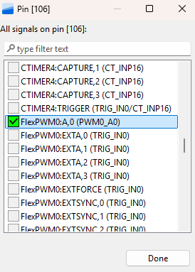
In the Pins Tool, with the current project selected, create a new Functional Group BOARD_InitPins. With the current project and BOARD_InitPins selected, in the Pins View select P3_0. In the dialog select FlexPWM0:A,0 (PWM0_A0) and click OK.
Click Update Code and click OK in the dialog. Once you've returned to the develop perspective, in your project folder, under board, open pin_mux.c. Scroll down to the bottom of the file or click BOARD_InitPins(void) : void in the Outline View. You'll see P3_0 has been configured as PWM0_A0 and port mux has been set to kPORT_MuxAlt5.
Code
#include <stdio.h>
#include "board.h"
#include "peripherals.h"
#include "pin_mux.h"
#include "clock_config.h"
#include "fsl_debug_console.h"
#include "fsl_pwm.h"

static void PWM_Setup(void)
{
    pwm_signal_param_t pwmSignal[1];

    pwmSignal[0].pwmChannel       = kPWM_PwmA;
    pwmSignal[0].level            = kPWM_HighTrue;
    pwmSignal[0].dutyCyclePercent = 50;
    pwmSignal[0].pwmchannelenable = true;

    PWM_SetupPwm(FLEXPWM0, kPWM_Module_0, pwmSignal, 1, kPWM_EdgeAligned, 1000UL,
                 CLOCK_GetFreq(kCLOCK_MainClk));
}

int main(void) {

    pwm_config_t pwmConfig;
    uint32_t pwmVal = 4;

    BOARD_InitBootPins();
    BOARD_InitBootClocks();
    BOARD_InitBootPeripherals();
#ifndef BOARD_INIT_DEBUG_CONSOLE_PERIPHERAL
    BOARD_InitDebugConsole();
#endif
    BOARD_InitPins();

    PWM_GetDefaultConfig(&pwmConfig);

    pwmConfig.prescale = kPWM_Prescale_Divide_1;
    pwmConfig.reloadLogic = kPWM_ReloadPwmFullCycle;
    pwmConfig.pairOperation   = kPWM_Independent;
    pwmConfig.enableDebugMode = true;

    if (PWM_Init(FLEXPWM0, kPWM_Module_0, &pwmConfig) == kStatus_Fail)
    {
	    PRINTF("PWM initialization failed\n");
	    return 1;
    }

    pwm_fault_param_t faultConfig;
    faultConfig.faultClearingMode = kPWM_Automatic;
    faultConfig.faultLevel = false;
    faultConfig.enableCombinationalPath = false;
    faultConfig.recoverMode = kPWM_NoRecovery;
    PWM_SetupFaults(FLEXPWM0, kPWM_Fault_0, &faultConfig);
    PWM_SetupFaults(FLEXPWM0, kPWM_Fault_1, &faultConfig);
    PWM_SetupFaults(FLEXPWM0, kPWM_Fault_2, &faultConfig);
    PWM_SetupFaults(FLEXPWM0, kPWM_Fault_3, &faultConfig);

    PWM_Setup();

    PWM_SetPwmLdok(FLEXPWM0, kPWM_Control_Module_0, true);

    PWM_StartTimer(FLEXPWM0, kPWM_Control_Module_0);

    while(1)
    {
    	SDK_DelayAtLeastUs((1000000U / 1000UL) * 10, 180000000U);

        pwmVal = pwmVal + 1;

        if (pwmVal > 100)
        {
            pwmVal = 0;
        }

        PWM_UpdatePwmDutycycle(FLEXPWM0, kPWM_Module_0, kPWM_PwmA, kPWM_EdgeAligned, pwmVal);

        PWM_SetPwmLdok(FLEXPWM0, kPWM_Control_Module_0, true);
    }
}
Wiring
Conclusion
You have learned how to dim an LED using PWM. You have also learned that the PWM driver for the FRDM MCX A346 is designed for motor control which requires safety features which aren't required for dimming an LED. In a future article, I will show why CTimer is often a more appropriate choice for lightweight tasks like LED dimming.